 Skip to content
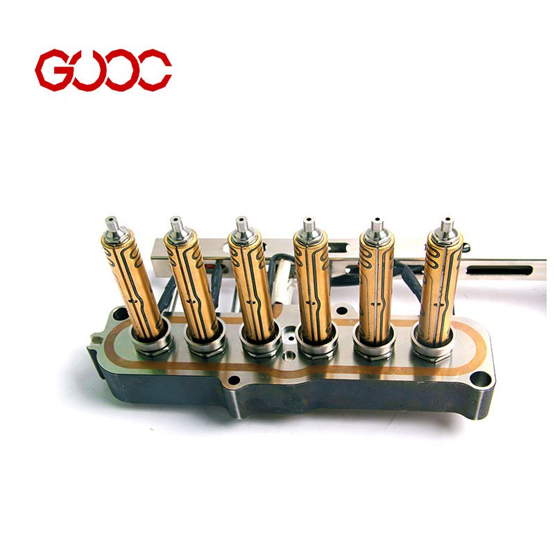
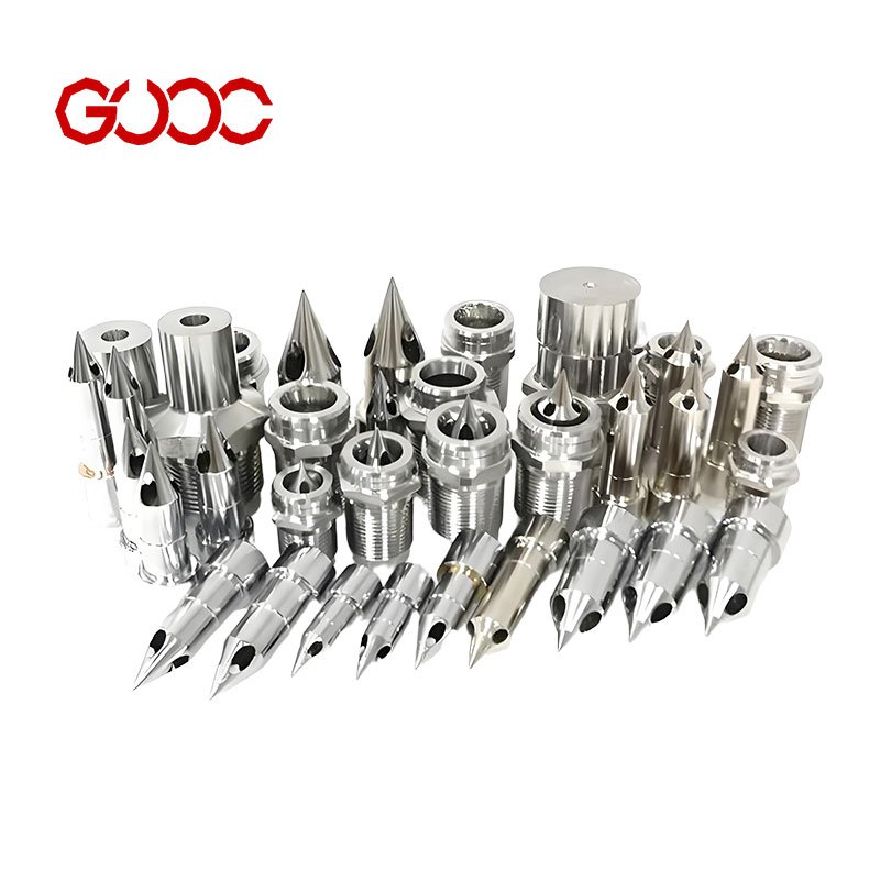
Identifying Your Thermocouple Architecture in Hot Runner Systems
When working with hot runner system nozzle thermocouple wiring, correctly identifying the thermocouple architecture is crucial for accurate temperature control and electrical integrity.
Grounded vs. Ungrounded Thermocouple Junctions
- Grounded Junctions
- The thermocouple junction is directly bonded to the metal sheath of the nozzle.
- Advantages: Faster response time due to direct thermal conduction; ideal for rapid temperature changes in injection molding.
- Disadvantages: Higher susceptibility to electrical noise interference and ground loops; signal can be affected by machine power fluctuations.
- Ungrounded Junctions
- The junction is electrically isolated inside the thermocouple sheath.
- Advantages: Reduced noise interference, resulting in cleaner signals for precise PID controller connection.
- Disadvantages: Slightly slower response time compared to grounded junctions; requires proper shielding and wiring separation.
Selection Tip: For injection molding systems sensitive to electrical noise, use ungrounded junction thermocouples to minimize erroneous temperature readings and improve overall process stability.
Thermocouple Calibration Types: Type J and Type K
- Type J (Iron-Constantan)
- Suitable for temperature ranges approximately -210°C to 760°C.
- Commonly used due to cost-effectiveness in hot runner manifold assembly.
- Iron wire must be verified for integrity to avoid drift and inaccuracies.
- Type K (Chromel-Alumel)
- Usable from -270°C up to 1260°C; preferred for higher-temperature applications.
- More stable under oxidizing atmospheres and widely adopted in industrial sensor wiring diagrams.
Wire Testing and Maintenance Tips
- Conduct a physical inspection of both the positive and negative thermocouple wires; contamination or damage alters the thermoelectric voltage.
- Use a multimeter set to millivolts to check the open-circuit voltage relative to temperature known points.
- Confirm correct polarity before installation: positive lead (typically non-magnetic or chromel for Type K) versus negative lead, following ANSI or IEC color coding standards.
By correctly identifying your thermocouple architecture and its calibration type, technicians avoid common pitfalls such as reverse polarity error or unstable temperature readings essential for injection molding temperature control.
Decoding Global Wiring Color Standards for Hot Runner System Nozzle Thermocouple Wiring
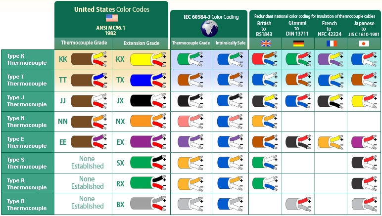
Understanding the wiring color codes for thermocouples in hot runner systems is essential for precise temperature control and avoiding faults. Different regions have established standards that define wire colors for Type J and Type K thermocouples, which are widely used in nozzle temperature monitoring.
ANSI Standards (North America)
In North America, the ANSI standard is the go-to reference for thermocouple wiring colors:
- Type K thermocouples use a yellow positive wire and a red negative wire.
- Type J thermocouples employ a white positive wire and a red negative wire.
It\’s important to note that the red wire always indicates the negative leg in ANSI wiring. Misidentifying polarity here can cause incorrect temperature readings or damage to sensitive PID controllers managing the injection molding temperature control.
IEC Standards (Europe/International)
The IEC wiring color codes differ, especially for Type K thermocouples:
- Type K positive wire is red, while the negative wire is yellow.
- Type J positive wire is red, with the negative being white.
This reversal from North American standards often causes confusion during installation or maintenance, especially in global operations using international hot runner manifold assemblies.
DIN Standards for Legacy German Machines
Older German equipment typically follows DIN standards, which align closely with IEC but sometimes feature slight color variations for certain thermocouple types. These legacy standards should be double-checked against machinery documentation to avoid miswiring, especially since some legacy connectors use unique pinouts.
Red Wire Polarity and Common Errors
The red wire polarity difference between ANSI and IEC systems is a frequent source of wiring faults:
- Assuming red is positive when it’s actually negative (or vice versa) can cause reverse polarity errors.
- This mistake may result in erratic temperature readings or alarm faults in multi-zone temperature controllers.
To prevent these issues, always verify the thermocouple type and regional wiring standards before connecting wires to heater coils or thermocouple extension cables. When working on hot runner system nozzle thermocouple wiring, cross-check colors and continuity carefully to avoid common installation errors.
For more detailed insights and practical wiring layouts, reviewing the hot runner manifold and control system connections can be incredibly helpful in ensuring your wiring meets global standards and operational reliability.
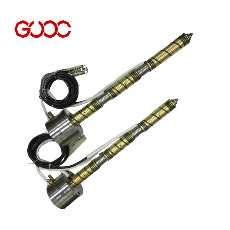
Step-by-Step Wiring Protocols for Nozzles
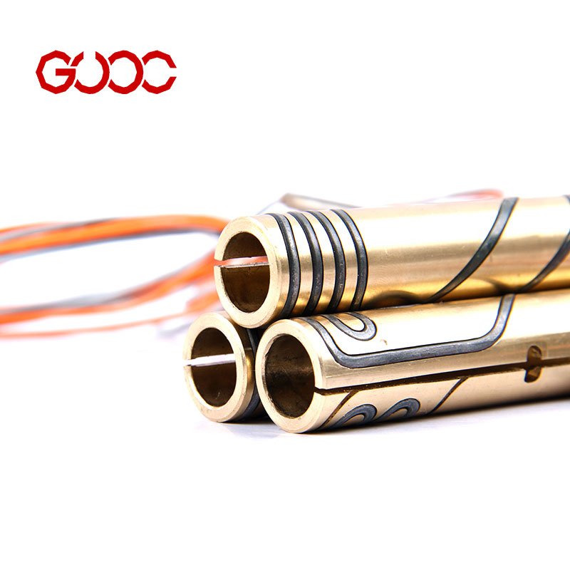
Getting your hot runner system nozzle thermocouple wiring right starts with good wire preparation. Use sharp tools to strip insulation cleanly without nicking the conductor. Crimp connectors tightly to ensure stable contacts, then cover joints with heat shrink tubing for insulation and mechanical protection. This basic care helps avoid loose connections and electrical shorts.
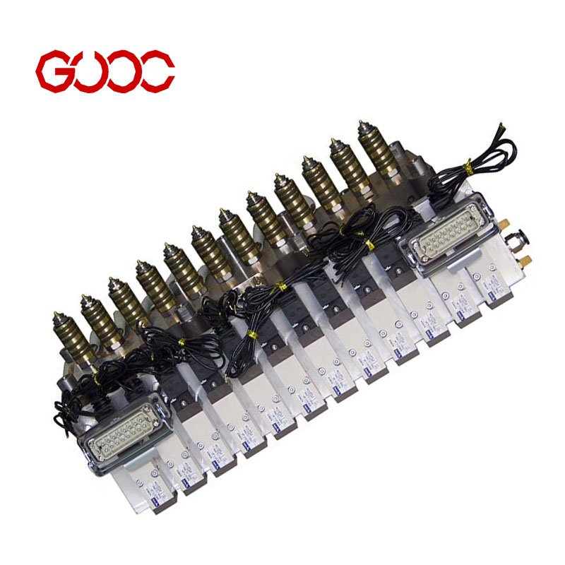
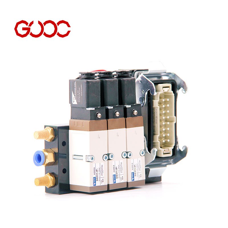
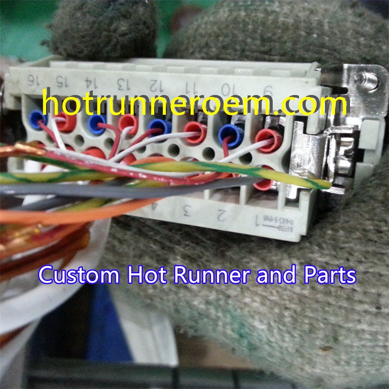
For heavy-duty connectors, know your pinouts well. Common nozzle setups use 5-pin or 24-pin connectors. Each pin has a dedicated function—some for heater power, others for thermocouple signals. Keep these lines separated physically inside the cable harness to greatly reduce electrical noise interference, which can cause inaccurate temperature readings. When routing wires, separate thermocouple leads from heater coils and power supplies whenever possible.
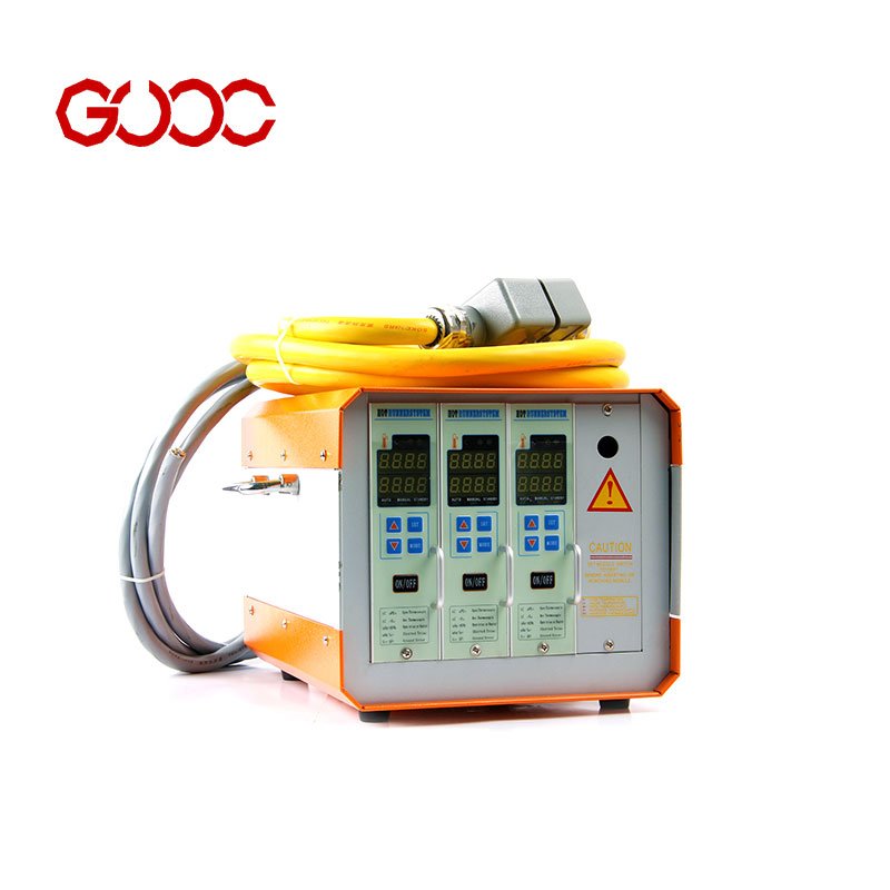
Zone configuration also matters. Cross-wiring heater and sensor zones can cause serious faults, including erratic thermocouple outputs or even component damage. Always double-check wiring diagrams during installation to verify each wire matches its designated zone. This is especially important in multi-zone temperature controllers managing complex hot runner manifold assembly setups.
If you want to dive deeper into nozzle wiring tips and pinout details, our resource on hot runner system nozzle design offers thorough insights.
By following clear wiring protocols and keeping heater and thermocouple circuits distinctly separated, you improve signal quality and system reliability for your injection molding temperature control needs.
Diagnosing Wiring Faults and Anomalies in Hot Runner System Nozzle Thermocouple Wiring
When dealing with hot runner system nozzle thermocouple wiring, quick and accurate fault diagnosis is vital to keep your injection molding temperature control running smoothly. Here\’s how to identify and fix common wiring issues:
Reverse Polarity Symptoms and Fixes
Swapping the thermocouple wires (positive and negative) causes reversed polarity, resulting in inaccurate or negative temperature readings. Signs include sudden temperature drops on the PID controller or erratic signals. To fix this:
- Confirm wire polarity by checking wire colors using ANSI or IEC references (remember red is often negative).
- Reverse the wires at the connector or junction box.
- Re-test the circuit to confirm stable readings.
Detecting Open Circuits with Continuity Tests
An open circuit in thermocouple wiring stops current flow and kills the signal, often rendering the temperature reading blank or constant at a failure value. To check for open circuits:
- Use a multimeter set to continuity mode.
- Test the wiring from the nozzle thermocouple tip through to the controller connector.
- Identify and replace any broken or damaged wiring sections promptly.
Checking Shorts to Ground Using Insulation Resistance Testers
Shorts between the thermocouple wires and ground can cause noisy or erratic readings and potentially damage your control equipment. Detect shorts by:
- Measuring insulation resistance between thermocouple wires and ground with a megohmmeter.
- Confirm resistance values meet safety thresholds (typically in megohms).
- Repair or replace any compromised insulation or wiring.
Identifying and Solving Electromagnetic Interference (EMI)
Electrical noise interference in molds frequently leads to unstable or fluctuating thermocouple readings. To mitigate EMI issues:
- Keep thermocouple wiring separated from heater power cables.
- Use shielded thermocouple extension cables designed for industrial environments.
- Secure wiring away from high-current sources and ground shields properly.
- If instability persists, consider installing noise filters or ferrite cores.
Proper troubleshooting not only restores reliable temperature sensing but also protects your multi-zone temperature controller and extends the life of your hot runner manifold assembly. For detailed wiring schematics and additional support, exploring our hot runner system nozzle thermocouple wiring resources can be very helpful.
Best Practices for Cable Management and Protection
Proper cable management is crucial for reliable hot runner system nozzle thermocouple wiring, especially in harsh injection molding environments. Here’s what to focus on:
Choose High-Temperature Insulation Materials
- Fiberglass insulation: Excellent heat resistance up to 550°C, suitable for most hot runner nozzles. It’s durable but less flexible.
- PTFE insulation: Handles temperatures up to about 260°C, offers great chemical resistance and flexibility, perfect for areas needing tight bends or movement.
Selecting the right insulation helps prevent melting or degradation that can cause short circuits or noise interference.
Smart Wire Routing Inside Mold Plates
- Keep thermocouple wires separate from heater power lines to minimize electrical noise that can disrupt precise temperature control in your multi-zone temperature controller setups.
- Route cables along designated channels or grooves within the mold to avoid crushing or abrasion during mold cycling.
- Avoid tight bends or sharp edges—stress points lead to wire failure over time.
Reliable Strain Relief at Nozzle Sensor Exits
- Use proper strain relief clamps or sleeves where cables exit the nozzle assembly. This prevents wire fatigue or breakage from repeated movement or vibrations.
- Heat shrink tubing combined with braided sleeving offers added mechanical protection and helps maintain consistent sensor connections.
- Check strain relief points regularly during mold maintenance to avoid unexpected wiring faults or false temperature readings.
By applying these cable management and protection practices, you ensure consistent thermocouple performance and reduce downtime in your hot runner manifold assembly. For comprehensive wiring solutions and quality components, check out our range of hot runner system parts.
