 Skip to content

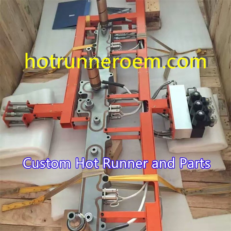
Step-by-Step Hot Runner System Design Process
Designing an effective hot runner system begins with a clear understanding of the mold’s requirements and the resin used. The first step is material selection, which is crucial for ensuring compatibility with the molten plastic and achieving optimal flow. Common plastics like PP, PFA, or PC each have unique thermal and flow characteristics that influence system design.
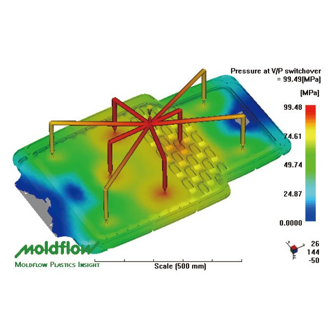
Next, mold flow analysis is performed to simulate how the molten plastic moves through the mold cavity. This helps identify potential issues such as flow imbalance or weld lines, allowing for adjustments before manufacturing. Accurate analysis ensures uniform filling, reduces defects, and improves part quality.
Once materials and flow are optimized, the focus shifts to gate location and gating options. Proper gate placement minimizes stress and ensures consistent filling. Gating options—such as valve gate or open gate—are chosen based on part design and application needs, balancing ease of molding with quality control.
The manifold channel layout and sizing are then carefully designed. The manifold distributes the molten plastic evenly to each cavity or drop. Proper channel sizing prevents pressure drops and ensures consistent temperature and flow, which are vital for maintaining the integrity of the mold cavity and preventing defects.
Finally, thermal expansion calculations and sealing design are critical to prevent leaks and maintain stable operation. The hot runner system must accommodate temperature fluctuations without compromising sealing or causing misalignment. Precise thermal management ensures reliable, high-quality production of injection molding parts.
Critical Considerations for Hot Runner Mold Design
Thermal Balance and Temperature Control
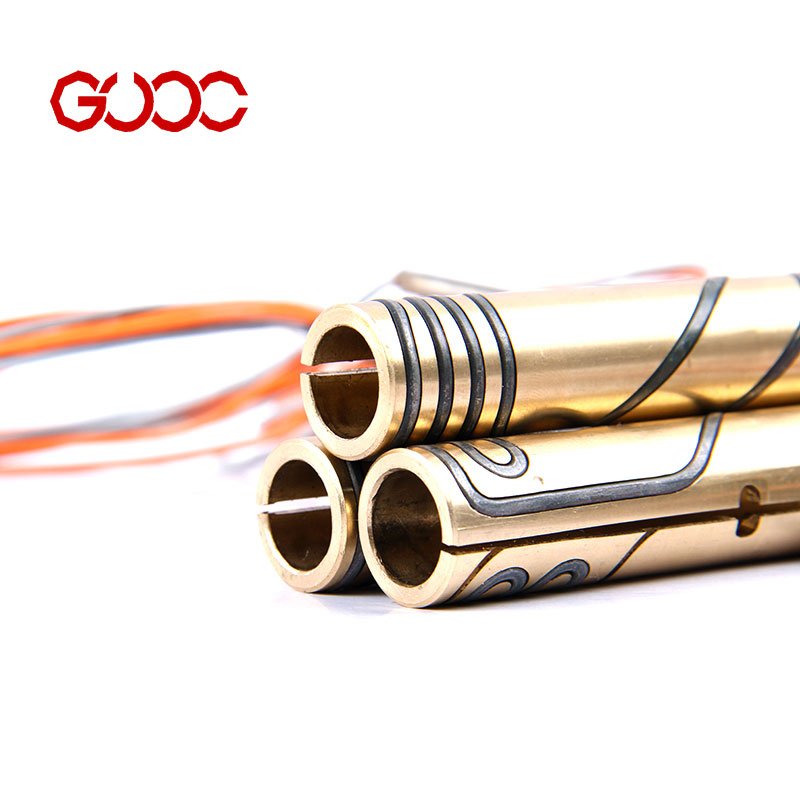
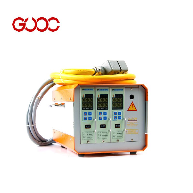
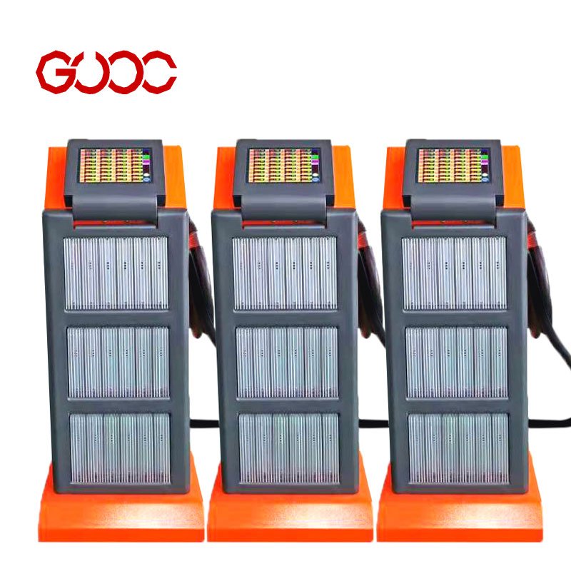
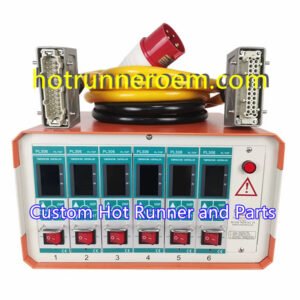
Achieving proper thermal balance is essential for hot runner system design to ensure uniform melt flow and prevent defects like warping or short shots. Precise temperature control of heating tubes and manifold is crucial, as uneven heating can cause inconsistent plastic resin flow. Using reliable temperature controllers, such as multi-zone PID systems, helps maintain stable temperatures across all zones, reducing thermal stress and prolonging system life. Proper thermal management directly impacts mold cavity quality and overall production efficiency.
Pressure Drop and Melt Flow Optimization
Managing pressure drop within the hot runner system is vital to ensure smooth molten plastic flow from the nozzle to the mold cavity. Excessive pressure can lead to flow imbalance, affecting part quality and cycle time. Optimizing gate location and gating options helps control melt flow, while careful manifold channel sizing minimizes pressure loss. A well-designed hot runner system balances pressure and flow, reducing melt stress and preventing issues like nozzle leakage or incomplete filling. Regular flow analysis can identify potential bottlenecks early.
Nozzle Selection and Tip Configuration
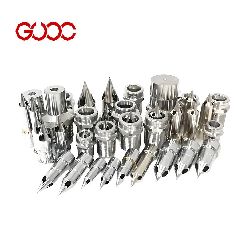
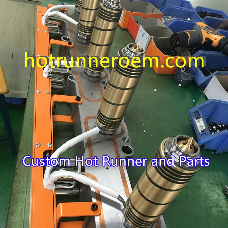
Choosing the right nozzle system and tip configuration is key to reliable hot runner system design. Valve gate nozzles offer precise control over melt flow, ideal for complex or high-precision parts. The torpedo tip design, for example, can improve sealing and reduce leakage risks. Proper nozzle selection depends on resin type, mold size, and application requirements. Ensuring the nozzle tip matches the mold cavity and gate type helps achieve optimal sealing and melt flow, leading to higher quality parts and longer system lifespan.
Selecting and Maintaining the Right Hot Runner System
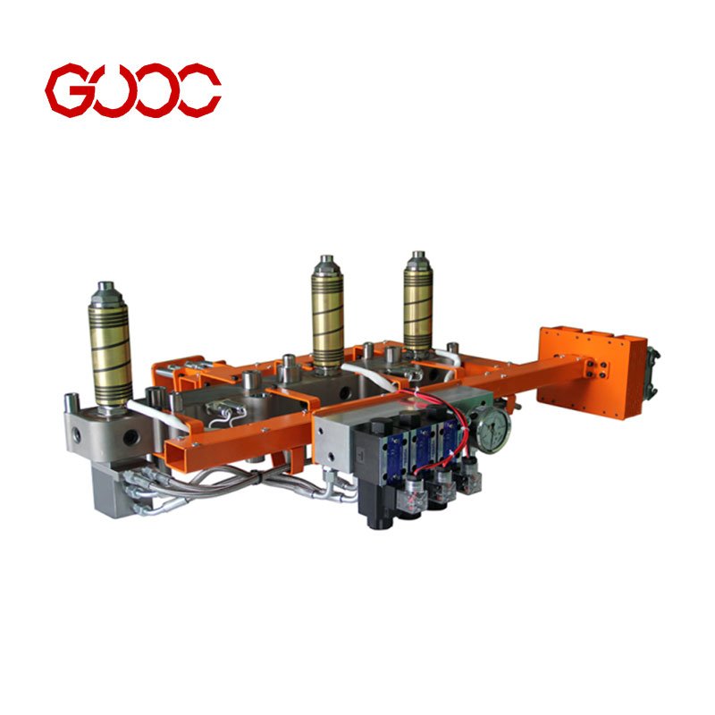
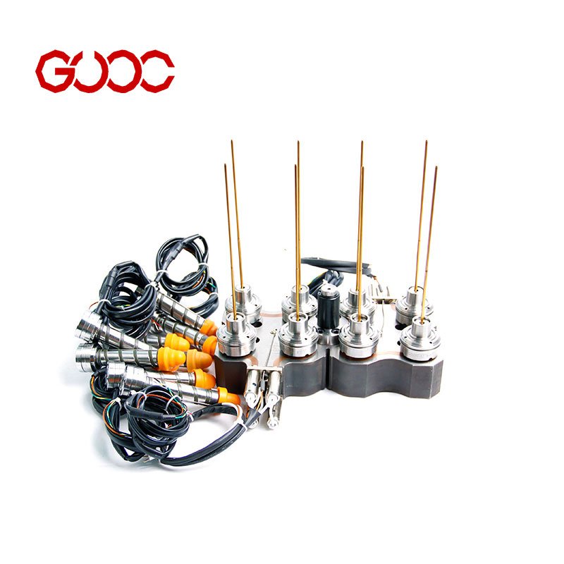
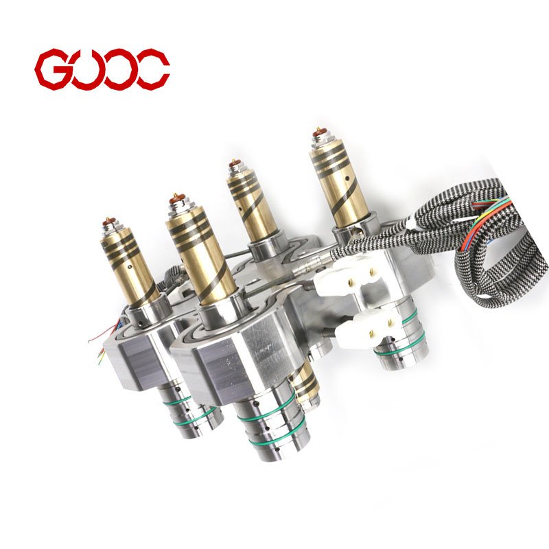
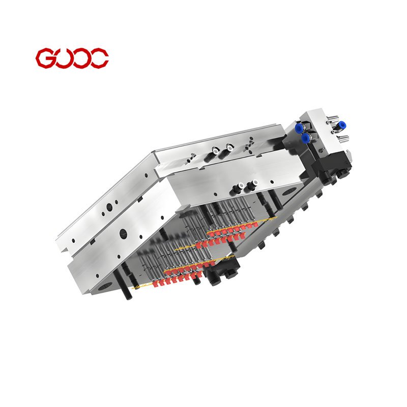
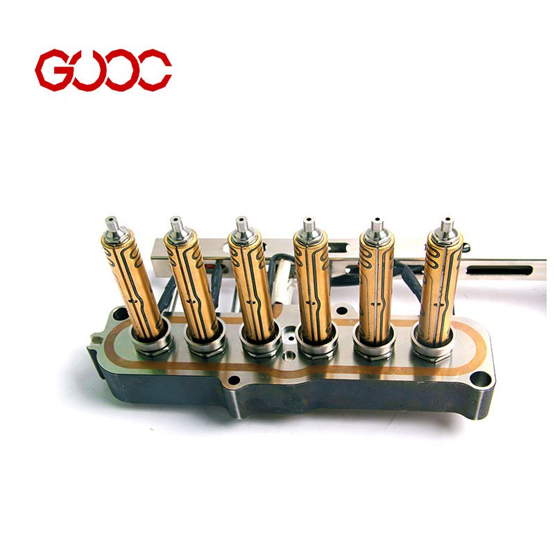
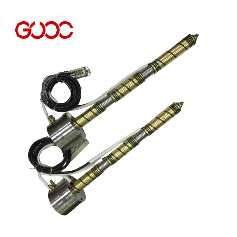
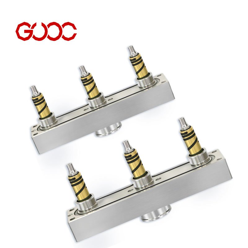
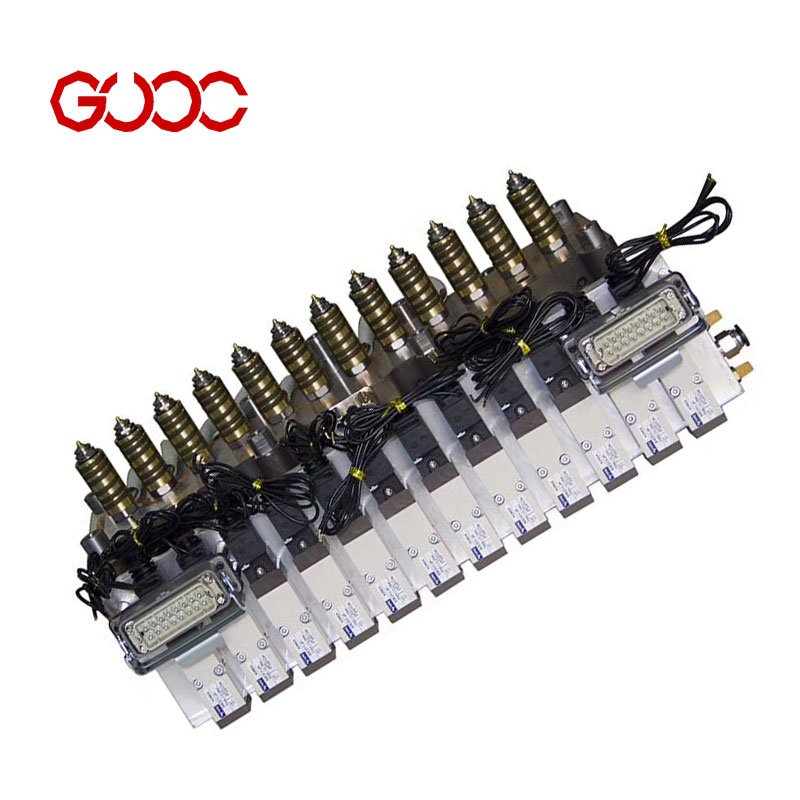
I choose the hot runner system design around the plastic resin, part size, and mold cavity layout first. That keeps molten plastic moving evenly and helps the injection molding process stay stable. For a quick system overview, I use the hot runner system page to match the nozzle system, heated manifold, and valve gate setup to the job.
Resin Compatibility and Application Requirements
Different plastic resin types need different temperature control and flow behavior. I check the resin, the part shape, and the application before I lock in the system.
| Check Point | What I Focus On |
|---|---|
| Resin type | PP, PFA, PES/PC, PA10T+30%GF, PBT+30%GF, PMMA, PEI ULTEM 1000, PC |
| Part use | Automotive, electronics, connectors, battery covers, tail lights |
| System choice | Valve gate, open gate, hot half, or extended nozzles |
| Mold fit | Cavity layout, melt path, and design balance |
A hot runner system manufacturer should also match the design to the real molding need, not just the drawing. That helps avoid mismatch between the heated manifold and the moldmaking plan.
System Maintenance, Cleaning, and Troubleshooting
I keep maintenance simple: inspect, clean, and check the control points often. That protects the nozzle system, keeps the temperature control steady, and lowers the risk of flow problems.
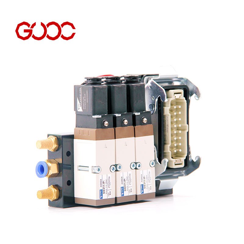
- Inspect wear points: heating tubes, cylinder control modules, and nozzles
- Check output stability: watch for uneven heating or temperature drift
- Clean carefully: remove residue before it builds up in the manifold area
- Confirm fit and sealing: look for signs of leak risk or poor contact
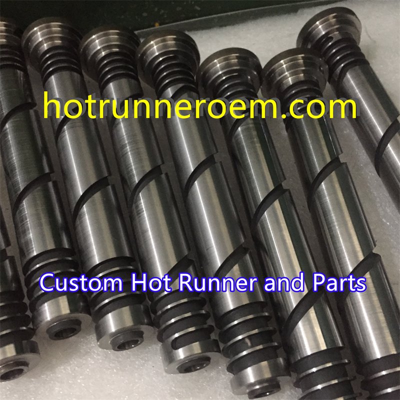
- Use replacement parts as needed: custom parts help keep the system running
When I source a setup, I also look at hot runner system suppliers that can support inspection, spare parts, and fast technical service. That matters when a system needs quick troubleshooting instead of long downtime.

 English
  Spanish
  French
  Portuguese
  Italian