 Skip to content
Understanding Hot Runner Thermocouples and Color Codes
Hot runner thermocouples are essential temperature sensors that ensure precise control of mold temperatures in injection molding. They are typically made from different types of thermocouple materials, each suited for specific temperature ranges and environments. Common types used in hot runner systems include K-type, J-type, and T-type thermocouples, selected for their stability and accuracy in high-temperature conditions.
Accurate wiring depends heavily on correct identification of polarity and color coding. Thermocouple wires are color-coded according to international standards to distinguish positive and negative leads. For example, in K-type thermocouples, the positive wire is often yellow, while the negative wire is red or green. Proper understanding of these color codes is crucial to prevent wiring errors that could lead to inaccurate temperature readings or system malfunctions. Ensuring correct wiring and color identification helps maintain the stability and efficiency of the hot runner system, which is vital for high-quality production.
Basic Principles of Hot Runner Thermocouple Wiring
Separating Power Lines and Thermocouple Signal Wires
In hot runner systems, it’s crucial to keep thermocouple signal wires separate from power lines. Mixing them can cause electrical interference, leading to inaccurate temperature readings. To ensure reliable data, use dedicated wiring paths for thermocouples and avoid crossing or bundling with high-current power cables. Proper separation minimizes noise and maintains precise temperature control, which is vital for consistent mold performance. When wiring, always follow best practices for insulation and shielding to prevent signal degradation. For detailed wiring techniques, you can refer to our hot runner thermocouple and heater suppliers.
Temperature Control Zone Wiring Principles
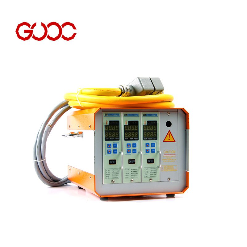
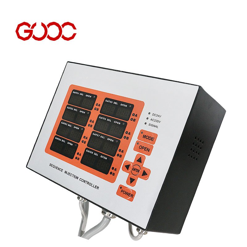
Wiring for each temperature control zone must be done systematically to ensure accurate feedback and stable operation. Connect thermocouples directly to designated input terminals on the hot runner temperature controllers, respecting the correct polarity. Proper wiring ensures the controller receives precise temperature data, enabling it to adjust heating elements effectively. Use heavy-duty connectors with clear pinout assignments, such as 16-pin or 24-pin connectors, to streamline installation and maintenance. Correct wiring setup is essential for maintaining consistent process quality and prolonging the lifespan of your hot runner system. For more on wiring configurations, see our hot runner temperature controllers.
Connecting Thermocouples to Hot Runner Nozzles and Manifolds
To ensure accurate temperature measurement, connect the hot runner thermocouple to the nozzle or manifold using proper wiring techniques. Carefully route the thermocouple wires through designated channels to avoid damage during mold operation. When connecting, verify the correct polarity—positive to positive, negative to negative—to prevent measurement errors. Use high-quality insulation to protect against heat and mechanical stress. For precise connections, refer to the specific hot runner system manufacturer’s guidelines, as different systems may have unique connection points. Proper wiring ensures stable temperature control and extends the lifespan of your hot runner temperature sensor.
Heavy-Duty Connector Pinout Assignments (16-Pin and 24-Pin)
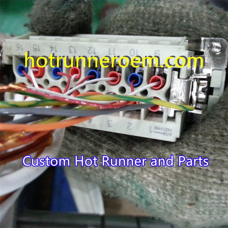
Heavy-duty connectors are essential for secure thermocouple wiring in hot runner systems. The 16-pin and 24-pin connectors have standardized pinout assignments that correspond to specific zones or sensors. For example, the pinout typically includes designated pins for thermocouple signals, power, and grounding. Always consult the connector’s wiring diagram to ensure correct pin connections. Proper pinout wiring prevents miscommunication between the thermocouple and the temperature controller, reducing the risk of false readings or damage. If you need detailed pinout information, you can refer to our guide on hot runner thermocouple heater suppliers.
Wiring Thermocouple Wires to Controller Modules
Connecting thermocouple wires to the temperature controller module requires attention to detail. First, strip the insulation carefully, exposing a clean section of wire. Connect the positive thermocouple lead to the positive input terminal, and the negative lead to the negative terminal on the controller. Ensure the wiring is tight and free from corrosion or loose connections, which can cause temperature fluctuations. Use shielded cables where possible to minimize electrical noise and interference. Proper wiring guarantees accurate temperature readings, which is critical for maintaining optimal mold performance. For reliable control, consider using a high-quality hot runner temperature controller, and always follow the manufacturer’s wiring instructions.
Essential Precautions for Hot Runner Wiring
Grounding and Shielding to Prevent Signal Interference
Proper grounding and shielding are critical when wiring hot runner thermocouples to ensure accurate temperature readings. Signal interference from nearby electrical components or static can cause fluctuations, leading to inconsistent mold temperatures. Always connect thermocouple shields to ground at a single point to avoid ground loops, which can introduce noise. Using shielded cables and routing them away from high-current power lines helps maintain signal integrity. Reliable grounding practices are especially important for hot runner temperature sensors, as they directly impact the quality of the final product.
Preventing Reverse Polarity and Connection Errors
Reverse polarity or incorrect wiring can cause false temperature readings or damage the thermocouple and control system. Always verify the positive and negative leads before connecting them to the hot runner temperature control module. Consistent color coding of thermocouple wires, such as red for positive and blue for negative, simplifies this process. Double-check all connections against the wiring diagram provided by your hot runner system manufacturer to prevent costly errors. Proper wiring ensures stable operation and prolongs the lifespan of your hot runner components.
Troubleshooting Common Thermocouple Wiring Issues
Diagnosing Temperature Reading Fluctuations and Errors
When you notice inconsistent temperature readings from your hot runner system, the first step is to check the wiring of your hot runner thermocouple. Fluctuations often stem from loose connections, damaged wires, or electromagnetic interference. Use a multimeter to verify circuit continuity and resistance levels. If readings are unstable, inspect the thermocouple wiring for proper grounding and shielding, as these factors can significantly affect signal stability. Ensuring your thermocouple is correctly wired according to OEM standards can prevent false readings and maintain stable mold temperatures. For more details on proper wiring practices, visit our hot runner temperature sensing wire.
Fixing Open Circuit and Short Circuit Faults
Open circuit faults occur when the thermocouple wiring is broken or disconnected, leading to no temperature signal. Short circuits happen when wires touch or insulation is compromised, causing incorrect readings or system errors. To fix these issues, first check all connections for secure contact. Replace any damaged wires or connectors, especially if insulation is worn or melted. Use a multimeter to perform resistance tests—an infinite resistance indicates an open circuit, while very low resistance suggests a short. Regular inspection and proper wiring installation, including correct pinout connections in heavy-duty connectors, are essential to prevent these faults. Proper wiring and maintenance ensure your hot runner system remains reliable and efficient.
Preventive Maintenance and Care for Hot Runner Wiring
Routine Inspection and Testing Procedures
Regular inspection of hot runner wiring is essential to ensure reliable operation. Use a high-precision multimeter or specialized testing tools to check for continuity, resistance, and proper insulation of thermocouple wires. Verify that all wiring connections are tight and free from corrosion or damage. Periodically test the hot runner temperature sensors and thermocouples to confirm accurate readings, which are crucial for maintaining stable mold temperatures. Consistent testing helps detect early signs of wear or faults, preventing costly downtime or defective products. For more detailed testing methods, consider consulting a professional or referring to trusted OEM guidelines, such as those from a reliable hot runner system manufacturer.
Correct Wiring Installation and Removal Practices
Proper wiring installation is key to avoiding future issues with hot runner thermocouples. Always follow the manufacturer’s wiring diagrams and specifications to ensure correct polarity and secure connections. When installing or removing thermocouples, handle wires with care to prevent damage to insulation or connectors. Use appropriate tools and avoid excessive force that could loosen or break delicate thermocouple wires. Proper routing of wires within the mold, away from moving parts and heat sources, reduces the risk of abrasion or short circuits. For OEM-grade hot runner systems, adhering to these practices helps maintain long-term performance and simplifies troubleshooting. Additionally, when replacing or upgrading wiring, always double-check pin assignments on heavy-duty connectors, such as 16-pin or 24-pin types, to ensure compatibility and safety.

 English
  Spanish
  French
  Portuguese
  Italian