




Understanding Moldflow Analysis in Hot Runner System Manufacturing
What is Moldflow Analysis?
Moldflow analysis is a plastic mold flow study used before production begins. For a hot runner system manufacturer, it is the first DFM step in the standard order process, placed before 2D dimension design, 3D model design, CNC machining, and assembly. It helps confirm how resin will move through the mold so the design can be adjusted early, not after tooling is already made.
The Role of Moldflow Simulation in Hot Runner Systems
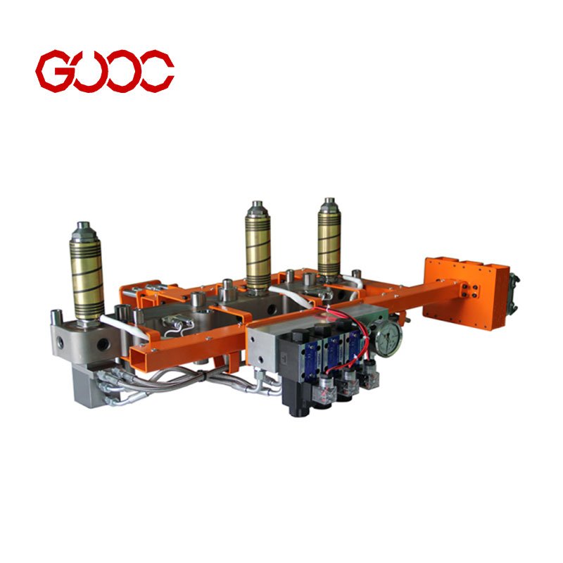
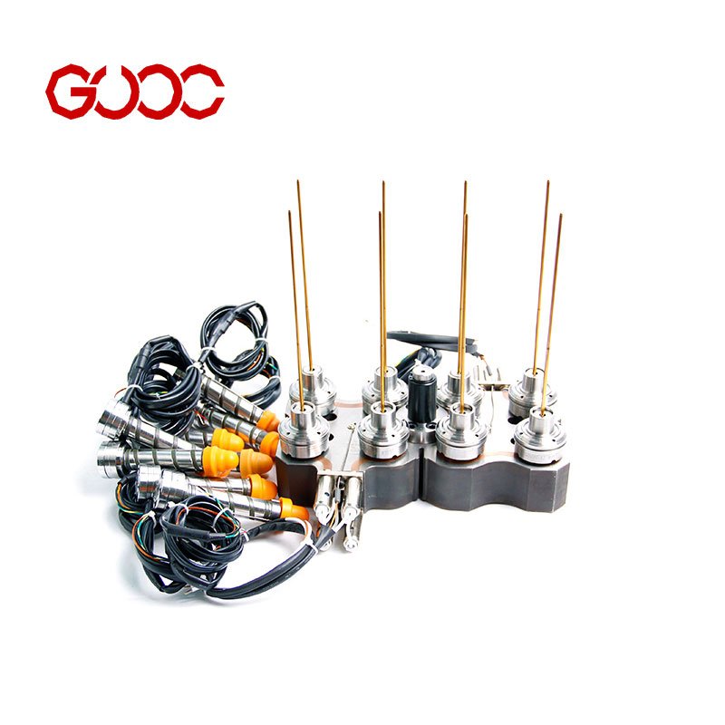
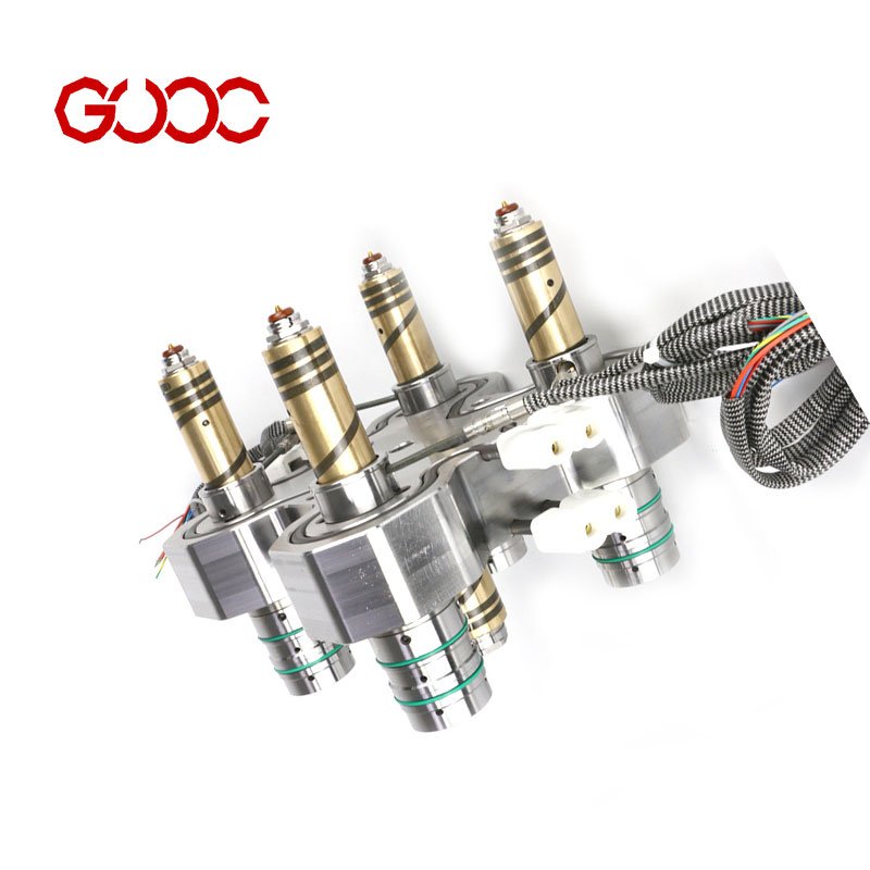
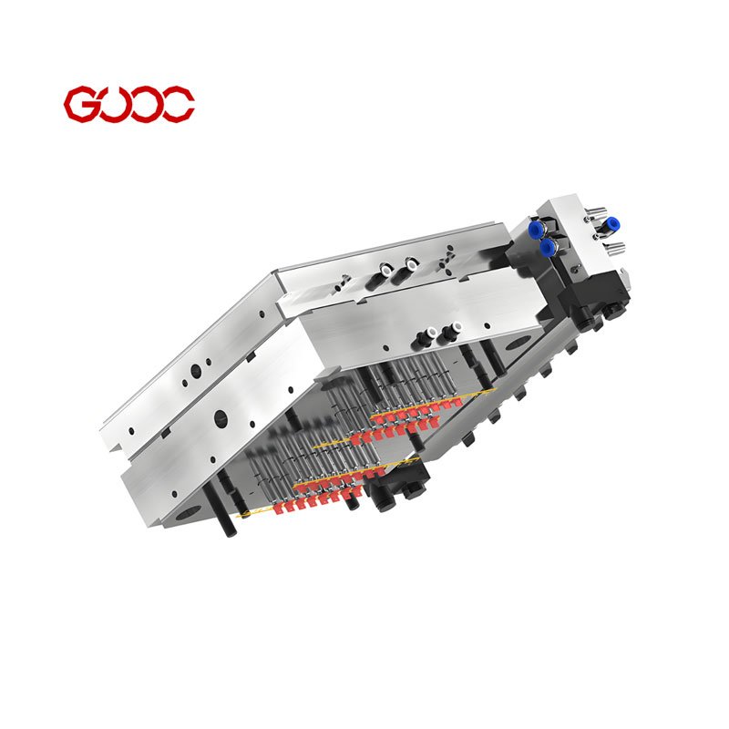
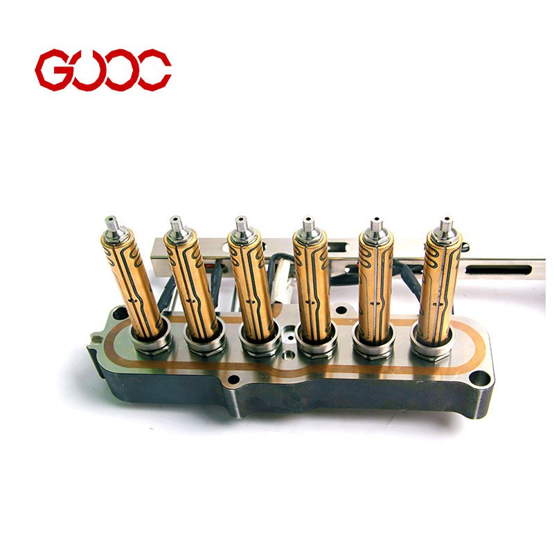
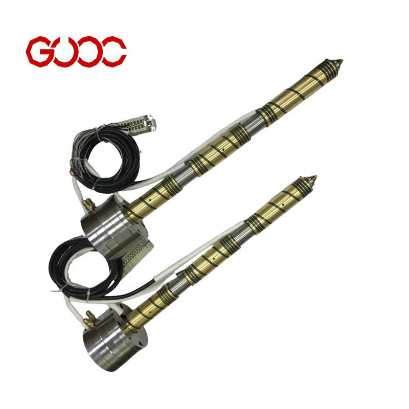
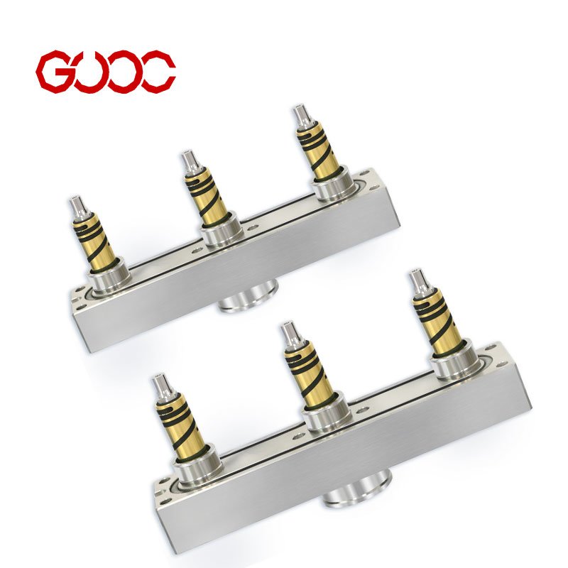
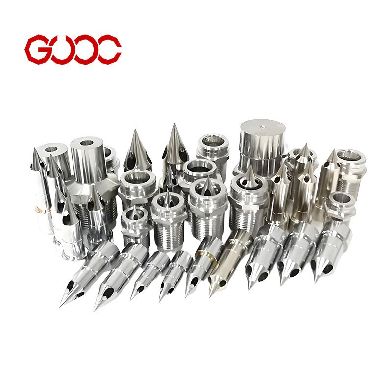
In hot runner system manufacturing, flow simulation helps match the right gate location, manifold layout, and nozzle design to the part and material. This is especially important for OEM hot runner projects that use different system types, such as:
– Valve gate hot runner systems
– Open gate hot runner systems
– Integrated systems
– Assembled hot runners
– Hot half systems
– Extended nozzles
By checking flow behavior before machining, manufacturers can support balanced filling, better thermal uniformity, and a more stable process for injection molding.
How Hot Runner Manufacturers Utilize Flow Simulation
A hot runner system manufacturer uses flow simulation to evaluate real application needs before production, including parts made with PP, PC, PBT + 30% GF, PA10T + 30% GF, PMMA, PES/PC, PFA/Teflon series, and PEI ULTEM 1000. This is practical for products such as automobile fenders, battery covers, chip wafer boxes, connectors, tail lights, fiber connectors, and chargers.
Key benefits include:
– Confirming gate location and runner balance
– Reducing pressure drop risk in complex layouts
– Supporting stable filling in multi-cavity designs
– Helping avoid material degradation from poor flow conditions
– Improving confidence before raw material prep and CNC machining
For custom hot runner OEM work, moldflow analysis gives the engineering team a clear basis for design, quotation, and production planning. It is a simple step, but it protects quality, saves time, and supports faster turnaround from concept to shipment.
Key Reasons Hot Runner Manufacturers Perform Moldflow Analysis
We start with moldflow analysis because gate location, manifold layout, and nozzle design decide whether a hot runner system runs smoothly or creates problems later. In our OEM workflow, this comes before 2D design, 3D modeling, CNC machining, and assembly, so we can match the resin, cavity count, and hot runner type before production.
Optimizing Gate Placement and Runner Balancing
Good gate placement helps control fill balance, pressure drop, and part appearance. Different jobs may need a valve gate system or an open gate setup, and the layout has to fit the part and resin. That is why I check the flow path first, not after machining.
- Better runner balance across multi-cavity molds
- Cleaner fill with the right gate location
- Less uneven load on the manifold and nozzle design
Related: hot runner gate types
Predicting and Eliminating Part Defects Early
Moldflow analysis helps me spot likely issues before steel is cut. That lowers the risk of short shots, flow imbalance, and visible defects on parts like tail lights, connectors, chargers, and covers. Early checks also help protect surface quality on materials such as PMMA, PC, PP, and reinforced resins.
Evaluating Thermal Uniformity Across Manifolds and Nozzles
Thermal uniformity matters because unstable heat can affect flow stability and part consistency. In hot runner system manufacturing, I use analysis to support a layout that works with the manifold and nozzle design instead of fighting them. That is especially important in multi-cavity and high-output jobs, where stable temperature control supports consistent injection molding results.
Reducing Mold Trial Costs and Tooling Rework
When flow is checked early, there is less trial-and-error later. That saves time on sampling, cuts rework risk, and makes the path from design to CNC machining and final assembly more direct. It also helps when we build integrated systems or assembled hot runners for complex applications.
- Fewer mold trials
- Lower tooling rework risk
- Faster quotes and DFM output
Related: hot runner mold solutions
Critical Types of Moldflow Analysis for Hot Runner Systems
Fill Analysis for Flow Front and Pressure Evaluation
Fill analysis is essential for understanding how the molten plastic flows through the mold and hot runner system during injection molding. It helps identify potential issues with flow front progression, pressure drops, and gate performance. By simulating the flow, manufacturers can optimize gate location and runner design to ensure uniform filling, especially in complex or high-cavitation molds. This step reduces the risk of incomplete fills or weld lines, leading to higher quality parts. For detailed insights on flow behavior, many hot runner system manufacturers rely on advanced mold flow analysis.
Pack Analysis for Shrinkage and Density Control
Pack analysis focuses on how the part solidifies after filling, ensuring proper packing pressure and timing to control shrinkage and density. This analysis helps prevent defects like sink marks or voids, which can compromise part strength and appearance. Proper pack analysis supports the use of high-performance resins and complex geometries, maintaining consistent part quality. It’s a critical step for optimizing the overall injection molding process and ensuring that the hot runner system delivers reliable, defect-free parts.
Cooling Analysis for Heat Dissipation and Cycle Time
Cooling analysis evaluates how heat is removed from the mold and hot runner components during each cycle. Effective thermal management ensures uniform cooling, which is vital for dimensional stability and part quality. Proper cooling reduces cycle time, increasing production efficiency. In high-precision applications, such as optical or electronic parts, thermal uniformity is crucial. This analysis helps optimize the design of cooling channels and temperature distribution, directly impacting the performance of the hot runner system.
Warp Analysis for Part Geometry and Stability
Warp analysis predicts how the part may deform during cooling and solidification, affecting overall geometry and stability. By simulating potential warping, manufacturers can adjust mold design and process parameters to minimize distortions. This is especially important for parts requiring tight tolerances or complex shapes. Incorporating warp analysis into the development of hot runner systems ensures parts meet specifications, reducing rework and scrap, and supporting consistent production quality.
Impact of Thermal Control on Moldflow Performance
Preventing Shear Heating and Polymer Degradation
In hot runner injection molding, thermal control is not optional. If the manifold or nozzle design runs too hot, the resin can see uneven heat, higher shear heating, and unstable flow. That can raise the risk of material degradation and make the melt harder to control.
Moldflow analysis helps me spot these problems early by showing how the material moves through the runner and gate location before machining starts.
- It helps check thermal uniformity across the hot runner system.
- It shows where pressure drop may rise and where flow may get stressed.
- It supports better gate and nozzle design for stable processing.
Balancing Manifold Temperatures for Multi-Cavity Molds
For multi-cavity molds, temperature balance matters even more. A hot runner system manufacturer has to keep the manifold and nozzles aligned so each cavity fills in a controlled way. When temperatures drift, flow balance changes fast.
That is why I use plastic mold analysis as part of the DFM stage. It supports better runner balance and helps match the system layout to real resin behavior, including cases like 32-drop hot half structures and other high-cavity designs.
Optimizing Temperature Controllers with Simulation Data
Simulation results also help shape the controller setup. With the right data, I can better plan how integrated temperature controllers, sequence injection timer controllers, and temperature control boxes should support the system during production.
This is especially useful when the job needs stable thermal control for different resin types and custom OEM builds. It also makes it easier to connect design decisions with the right hot runner temperature controllers for consistent output.
Key gains from this step:
- More stable thermal control
- Better thermal uniformity
- Lower risk of material degradation
- Cleaner flow through the manifold and nozzle design
- More consistent injection molding results
Business and Operational Advantages for System Manufacturers
Accelerating Time-to-Market for Custom Mold Designs
Performing moldflow analysis early in the development process significantly speeds up bringing custom hot runner systems to market. By simulating the resin flow and gate placement virtually, manufacturers can identify potential issues before physical prototyping. This reduces the number of mold trials needed, saving both time and costs. Faster development cycles mean manufacturers can respond quickly to customer demands and stay ahead in the competitive injection molding industry.
Validating Advanced Resin Selections and Flow Behavior
Moldflow simulation allows manufacturers to validate how advanced resins, such as high-temperature or reinforced materials, will behave during injection molding. This is crucial for ensuring proper flow, pressure drop, and thermal uniformity across the manifold and nozzles. By understanding flow behavior upfront, manufacturers can optimize system design to accommodate complex materials, reducing risks of material degradation or shear heating, which can compromise part quality.
Enhancing Production Yield and Part Quality Consistency
Using moldflow analysis, hot runner system manufacturers can improve production yield by predicting and controlling critical factors like fill pattern, packing, and cooling. This leads to more consistent part quality and fewer defects such as warping or sink marks. Optimized flow and thermal management also mean fewer rework cycles, higher throughput, and better overall efficiency. These benefits directly translate into cost savings and stronger customer trust in the reliability of the systems produced.
Best Practices for Integrating Moldflow Analysis
When to Execute Moldflow Analysis During Design
I start moldflow analysis at the DFM stage, before 2D drawing work, 3D model design, and CNC machining. That is the safest point to check whether the resin, gate location, and runner layout make sense for the part.
For a hot runner system manufacturer, this matters most when the job needs:
- Valve gate or open gate selection
- Integrated or assembled hot runner layout
- Multi-drop balancing, such as 32-drop hot half setups
- Tight schedules for 12–24 hour quotes, fast sampling, and short production lead times
A simple rule works well:
| Design stage | What I check |
|---|---|
| Before hardware design | Resin behavior, gate location, flow balance |
| Before machining | Runner layout, manifold fit, nozzle design |
| Before assembly | Control needs, part stability, inspection points |
I keep the flow study tied to real application cases, like PP, PC, PMMA, PA10T + 30% GF, PBT + 30% GF, PES/PC, PFA/Teflon series, and PEI ULTEM 1000. That keeps the design grounded in the actual mold job, not guesswork.
Translating Simulation Results into Hot Runner Hardware Specifications
Once the moldflow result is clear, I turn it into practical hardware decisions:
- Gate location: place it where flow balance and part finish are easier to control
- Nozzle design: match the melt path to the part geometry
- Manifold layout: keep the system balanced across all cavities
- Temperature control: align with the hot runner system and controller setup
This is where hot runner system design becomes real engineering, not just a drawing task. The analysis tells me what to lock in before production starts.
| Simulation output | Hardware decision |
|---|---|
| Flow balance | Manifold and runner layout |
| Pressure drop | Nozzle path and gate position |
| Thermal behavior | Temperature control plan |
| Part behavior | Valve gate or open gate choice |
For local and global buyers, this helps reduce back-and-forth, protect NDA drawings, and move faster from CAD upload to quote and DFM review.
Iterative Testing for Complex High-Cavitation Applications
High-cavitation jobs need more than one pass. I use iterative checks when the system has:
- Many drops
- Tight part tolerances
- Reinforced or specialty resins
- Mixed requirements across cosmetic and functional parts
That is especially useful for connectors, covers, optical parts, and other precision injection molding jobs where thermal uniformity, shear heating, and pressure drop can affect results.
My process is straightforward:
- Run the first moldflow review
- Adjust gate location or manifold balance
- Refine nozzle design and control setup
- Recheck before machining and assembly
This approach supports better part consistency, fewer trial issues, and smoother lot inspection later. It also fits a fast OEM workflow with hourly QC, 100% pre-shipment inspection, and clear build control from the start.
 English
  Spanish
  French
  Portuguese
  Italian