 Skip to content



What Is Moldflow Analysis in Hot Runner Mold Design?
Understanding Moldflow Simulation Technology
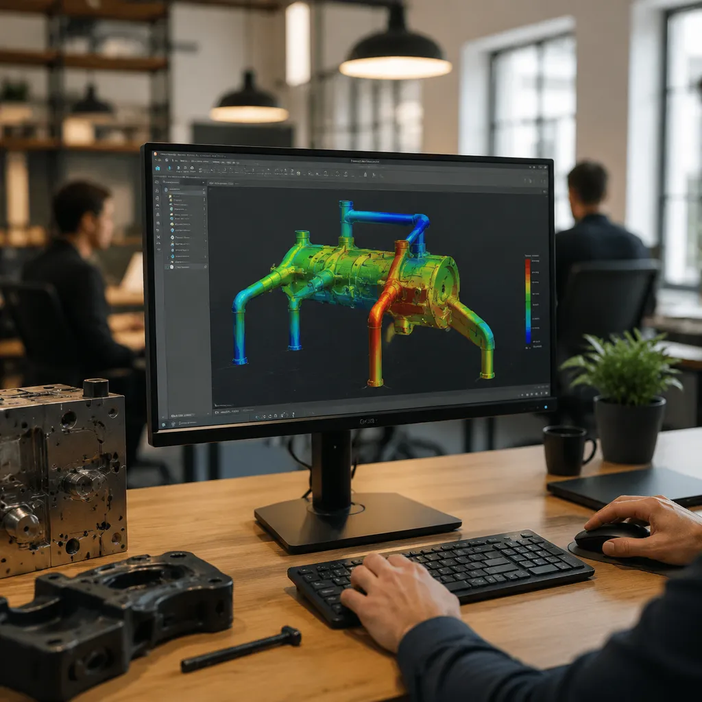
Moldflow analysis is a critical tool in hot runner mold design that uses advanced simulation technology to predict how plastic melts and fills the mold cavity. It helps identify potential issues like air traps, weld lines, and warpage before manufacturing begins. By analyzing melt temperature, pressure drops, and flow paths, engineers can optimize the mold’s performance, ensuring uniform filling and reducing defects. This technology provides precise insights into how the hot nozzle and cooling channels will behave, allowing for adjustments that improve part quality and process efficiency.
Overview of Hot Runner Injection Molding Systems
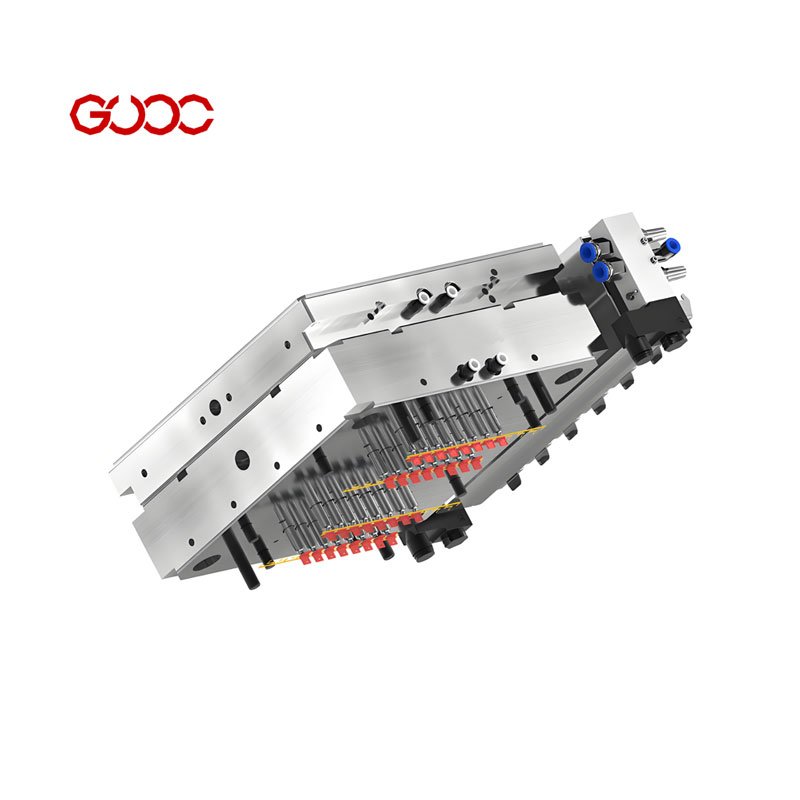
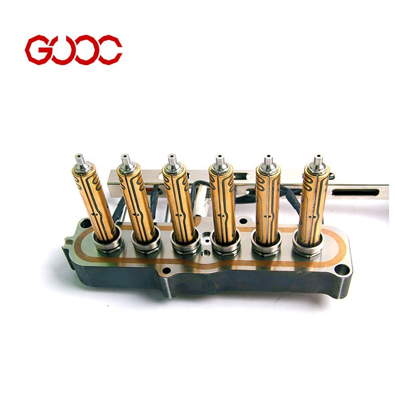
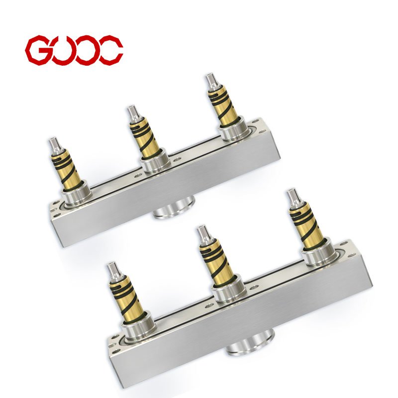
Hot runner systems are designed to deliver molten plastic directly into the mold cavities through heated nozzles and manifolds. They enable multi-cavity molds to produce parts efficiently with minimal waste. Proper design of gate locations, runner sizing, and cooling channels is essential for achieving uniform filling and preventing issues like air traps or weld lines. As a leading hot runner system manufacturer, we focus on integrating moldflow analysis to refine these components, ensuring optimal gate placement and pressure management. This results in better control over melt temperature, reduced cycle times, and higher-quality parts.
Optimizing Thermal Balance and Temperature Distribution
Maintaining a uniform melt temperature across the hot runner system is crucial for consistent part quality. Moldflow analysis helps identify hotspots and cold zones, allowing us to optimize cooling channels and heater placement. Proper thermal balance prevents uneven flow and reduces the risk of weld lines or air traps, ensuring smooth, defect-free molding. By simulating heat dissipation, we can fine-tune the hot nozzle and cooling system to achieve optimal temperature distribution, which is vital for multi-cavity molds and complex parts.
Minimizing Pressure Drop in the Runner Manifold
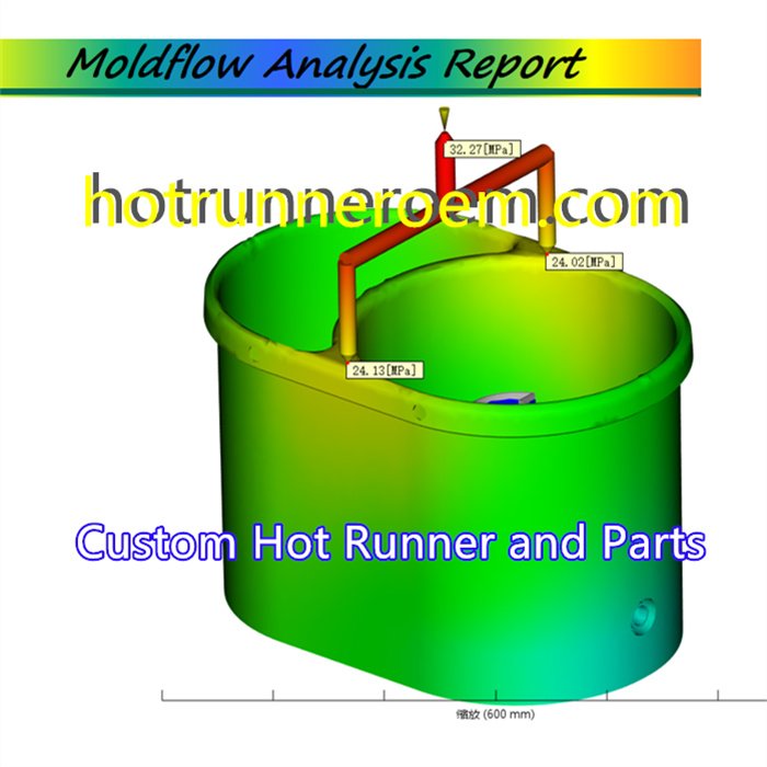
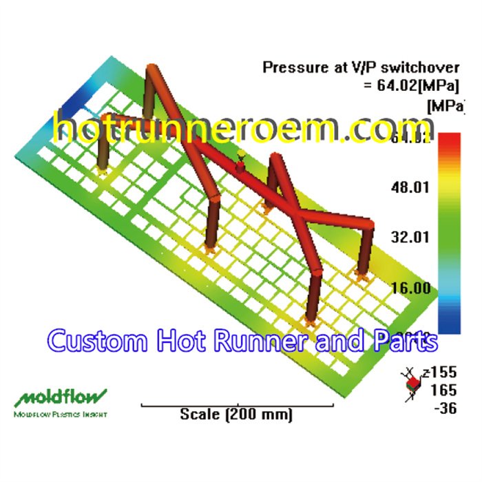
A key challenge in hot runner system design is controlling pressure drops that can cause inconsistent filling or flow hesitation. Moldflow simulation allows us to analyze flow paths and adjust gate locations, runner sizing, and manifold layout for minimal pressure loss. This ensures uniform filling, especially in large or multi-cavity molds, reducing cycle times and preventing issues like melt temperature fluctuations. Effective pressure management also extends tool life and improves overall productivity.
Preventing Material Leakage and Thermal Degradation
Proper mold design with the help of moldflow analysis reduces the risk of material leakage and thermal degradation. By accurately predicting flow behavior, we can optimize gate types and positions, as well as the hot nozzle design, to prevent melt backflow and air traps. Controlling melt temperature and flow rate minimizes thermal stress on the resin, which is essential for high-performance materials like PFA or ULTEM. This approach ensures high-quality parts with minimal rework and longer mold lifespan.
Key Stages of Moldflow Analysis for Injection Molds
As a hot runner system manufacturer, I use Moldflow analysis to catch fill, cooling, and deformation problems before steel is cut. That helps me keep uniform filling, control pressure drops, and improve part quality from the start. For a deeper look at how I handle this step, my mold flow analysis service for hot runner designs is built around early DFM checks and practical production results.
Mold Filling and Packing Simulation
This is where I check how melt moves through the hot nozzle, manifold, and gate locations. The goal is simple: get balanced flow and avoid defects before tooling starts.
- Spot air traps and weld lines early
- Check whether the cavity fills evenly in multi-cavity molds
- Review filling pressure and packing behavior
- Confirm the melt stays stable at the right melt temperature
A good filling study helps me choose the right gate type and reduce the risk of short shots, burn marks, and uneven pack-out.
Cooling Analysis and Heat Dissipation
Cooling is just as important as filling. If heat is not removed evenly, the mold will cycle poorly and the part will shift shape.
- Review cooling channels for balance and efficiency
- Identify hot spots that can slow production
- Reduce uneven shrinkage caused by poor heat dissipation
- Support more stable cycle times and better part consistency
In hot runner work, thermal control matters a lot. When cooling is weak or uneven, the system can lose process stability fast.
Warpage and Deformation Prediction
Warpage analysis shows me how the part may bend, twist, or shrink after ejection. This is key for tight-tolerance parts and large cosmetic surfaces.
- Predict warpage before tooling changes become expensive
- Compare deformation risk across resin types and part geometries
- Adjust gate balance, packing, and cooling strategy
- Reduce rework caused by dimension drift
This stage is especially useful when the design has long flow paths, uneven wall thickness, or strict appearance requirements. It helps me turn analysis into a more reliable mold design, not just a report.
Optimizing Hot Runner Design Parameters with Moldflow
I use Moldflow analysis to lock in the key hot runner settings before metal cutting starts. That means better manifold layout, cleaner gate decisions, and tighter control of melt flow in multi-cavity molds. It also helps reduce pressure drops, air traps, weld lines, and warpage in the final part.
| Design point | What I check | Why it matters |
|---|---|---|
| Manifold layout | Flow balance, melt temperature, pressure drops | Helps keep filling stable across all cavities |
| Gate selection | Gate locations, gate type, part geometry | Supports cleaner fill and better surface quality |
| Valve timing | Open/close sequence, cavity balance, fill pattern | Improves control on complex parts |
Manifold Layout and Runner Sizing Optimization
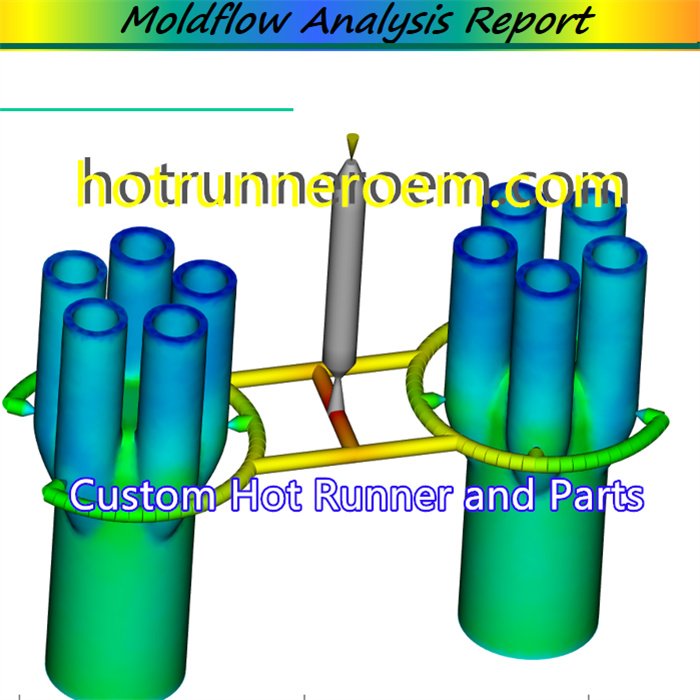
Manifold layout starts with uniform filling. I check how melt moves through the runner system so the hot nozzle and manifold size match the part demand, not just the machine setup. This is especially important in multi-cavity molds, where uneven flow can create pressure drops and visible defects.
- Balance flow across each cavity
- Reduce excess pressure loss in long paths
- Keep melt temperature steady from inlet to gate
Gate Location and Type Selection
Gate location has a direct impact on fill pattern, air traps, and weld lines. I use Moldflow to compare gate locations and choose the right gate type for the part, resin, and cavity count. For a clearer breakdown of common options, I also refer to our hot runner gate types guide.
- Place gates where flow can spread evenly
- Support cleaner appearance on visible surfaces
- Match the gate type to the material and part shape
Sequential Valve Gate Control and Timing
For larger parts or complex fills, sequential valve gate control helps me manage when each gate opens and closes. That gives better flow control, more stable packing, and fewer marks from uneven filling. With the right hot runner control setup, timing becomes part of the design, not just the machine setting.
- Set gate opening order to guide melt front movement
- Reduce hesitation and flow imbalance
- Improve part consistency in demanding applications
Major Benefits of Moldflow in Hot Runner Mold Manufacturing
In hot runner mold projects, the biggest risk is not the steel cut itself. It is finding flow problems too late. I use Moldflow analysis to catch those risks early, before CNC machining and assembly start. That is especially useful in our hot runner mold work, where gate locations, melt temperature, pressure drops, and cooling channels all affect the final part.
Predicting and Preventing Common Molding Defects
Moldflow helps us see where the process may go wrong before production. That includes issues like:
- air traps
- weld lines
- warpage
- uneven filling
- local overheating
For a hot runner system manufacturer, this matters because the runner, hot nozzle, and gate design all work together. If the flow is uneven, the part quality suffers fast.
| Problem area | What Moldflow checks | Practical result |
|---|---|---|
| Gate locations | Flow balance and entry point impact | Better uniform filling |
| Runner path | Pressure drops and melt movement | Smoother flow |
| Cooling layout | Heat removal and temperature balance | Less warpage |
| Part geometry | Weak zones and trap points | Fewer defects |
Reducing Tooling Trial Costs and Iterations
Early Moldflow analysis makes DFM work more useful. Instead of relying on repeated trial runs, we can review the design first and adjust the layout before making the tool. That saves time and lowers the chance of expensive rework.
This is where our plastic mold analysis process adds value:
- review part shape and flow behavior
- check if the gate type fits the material
- confirm runner balance for multi-cavity molds
- refine the hot runner layout before production
For buyers, this means fewer tooling revisions and a cleaner start.
Shortening Cycle Times and Enhancing Part Quality
A better flow plan also supports faster, more stable molding. When melt flow is balanced and the cooling system is planned well, the part is easier to fill and control. That can help reduce cycle time pressure and improve repeatability.
| Benefit | What improves |
|---|---|
| Faster cycles | More stable filling and cooling |
| Better quality | Less warpage and fewer defects |
| More consistent output | Stable melt temperature and pressure control |
| Easier production | Fewer adjustments on the shop floor |
In our OEM workflow, this is one reason we combine Moldflow-style analysis with DFM review, drawing checks, and full-system design. It gives the project a stronger base before sampling and mass production.
When and How to Implement Moldflow in the Design Workflow
Integrating Moldflow in Early DFM
I put Moldflow into the first DFM review, before steel is cut, because that is where most costly mistakes are still avoidable. At this stage, I can check gate locations, uniform filling, cooling channels, and melt temperature behavior before the mold goes into CNC work. For a hot runner system manufacturer, this early step helps me spot air traps, weld lines, pressure drops, and warpage risks before they turn into rework.
- Review the part geometry and hot runner layout first
- Test filling balance for multi-cavity molds
- Adjust the manifold and hot nozzle setup before tooling starts
For a deeper look at the build side, I keep the hot runner system design process aligned with the analysis results, so the design and the simulation support the same target from the start.
Selecting Accurate Material Data
Moldflow is only useful when the input data is solid. I rely on accurate material characterization data for the resin being used, because flow behavior changes with each material grade, filler level, and processing window. If the data is off, the results for pressure drops, cooling, and deformation prediction can point in the wrong direction.
- Use the exact resin grade, not a similar substitute
- Match the melt temperature and processing settings to the real job
- Check the material data before finalizing the hot runner design
That is how I keep the analysis practical: early DFM review, correct material data, and a clear path from simulation to stable production.
 English
  Spanish
  French
  Portuguese
  Italian