 Skip to content
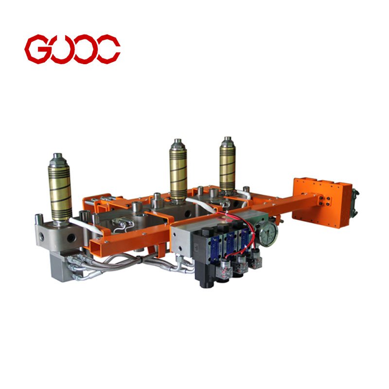
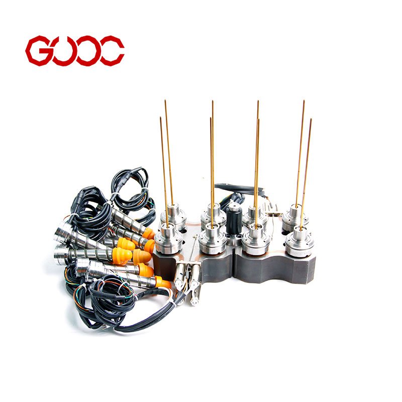
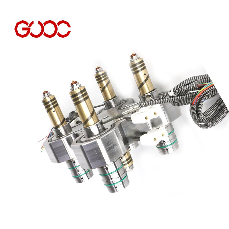
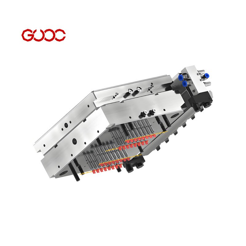
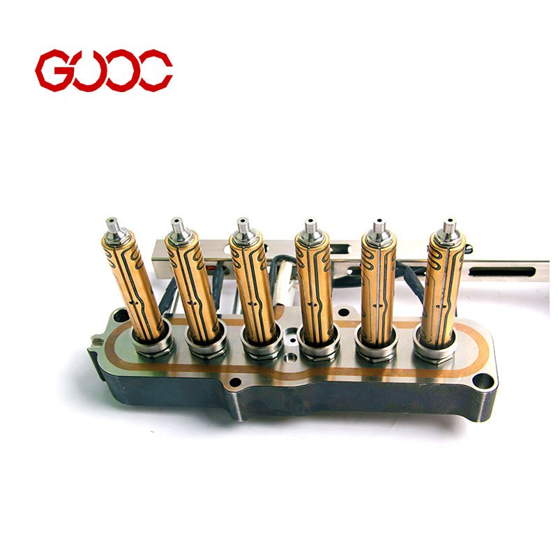
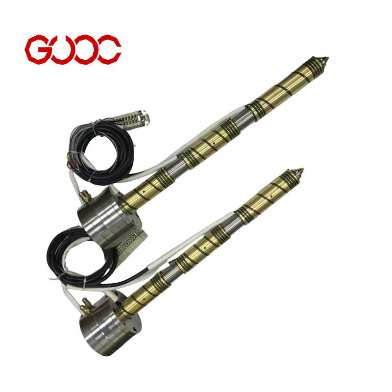
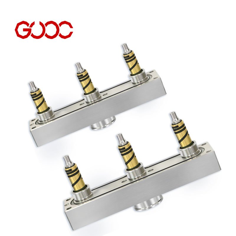
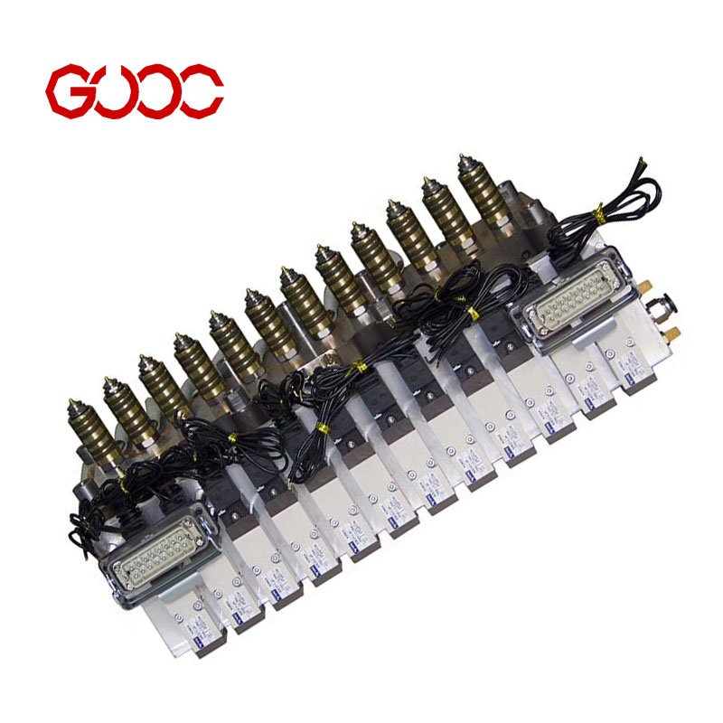
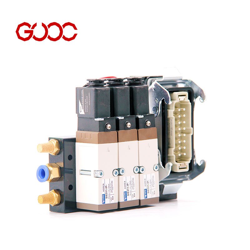
hot runner system mold controllers and cables
Product Overview: Precision Thermal Regulation Sets
Complete Package: Integrated Controller and Cable Solutions
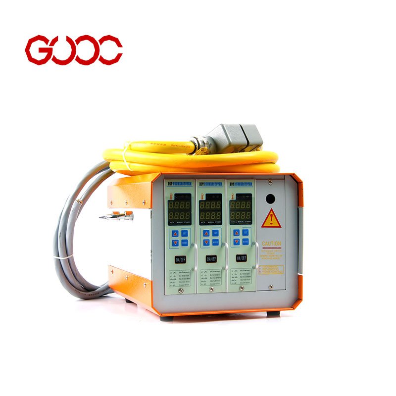
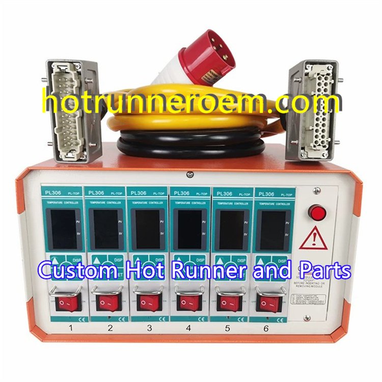
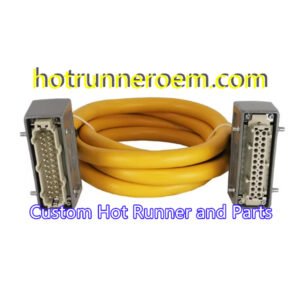
Our turnkey system features high-precision multi-zone temperature controllers paired with rugged, industrial-grade hot runner cable assemblies. Each set combines the mainframe’s advanced PID hot runner control modules with thermocouple interconnect cables and heavy-duty mold power cables, providing a seamless hardware integration for injection molding TCU operations.
Core Capability: Intelligent Control & Quick Setup
Equipped with PID auto-tuning algorithms, the controller optimizes temperature stability, minimizing thermal fluctuations and mold downtime. The Plug-and-Mold-ready design facilitates rapid mold heater connection sets, reducing setup complexity and ensuring consistent phase and amperage management across zones.
Compatibility Assurance: Global Standards Compliance
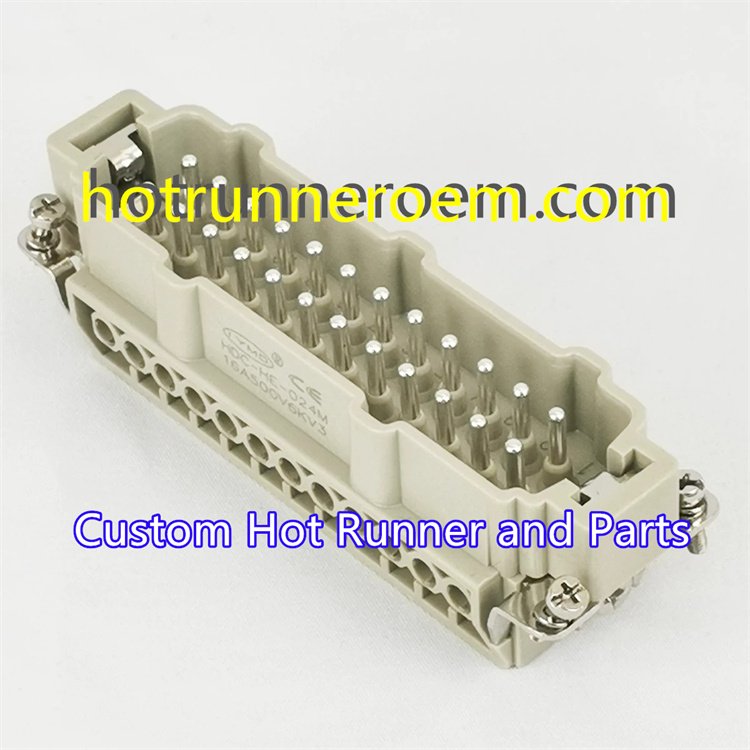
Designed for universal integration, the controller mainframe and cable assemblies comply with established hot runner interface standards including DME, Yudo, Husky, and Athena. Standard industrial rectangular connectors with 16-, 24-, and 48-pin variants guarantee reliable connectivity across diverse injection molding systems.
The Controller Mainframe: Technical Architecture
Modular Design: Flexible Zone Control
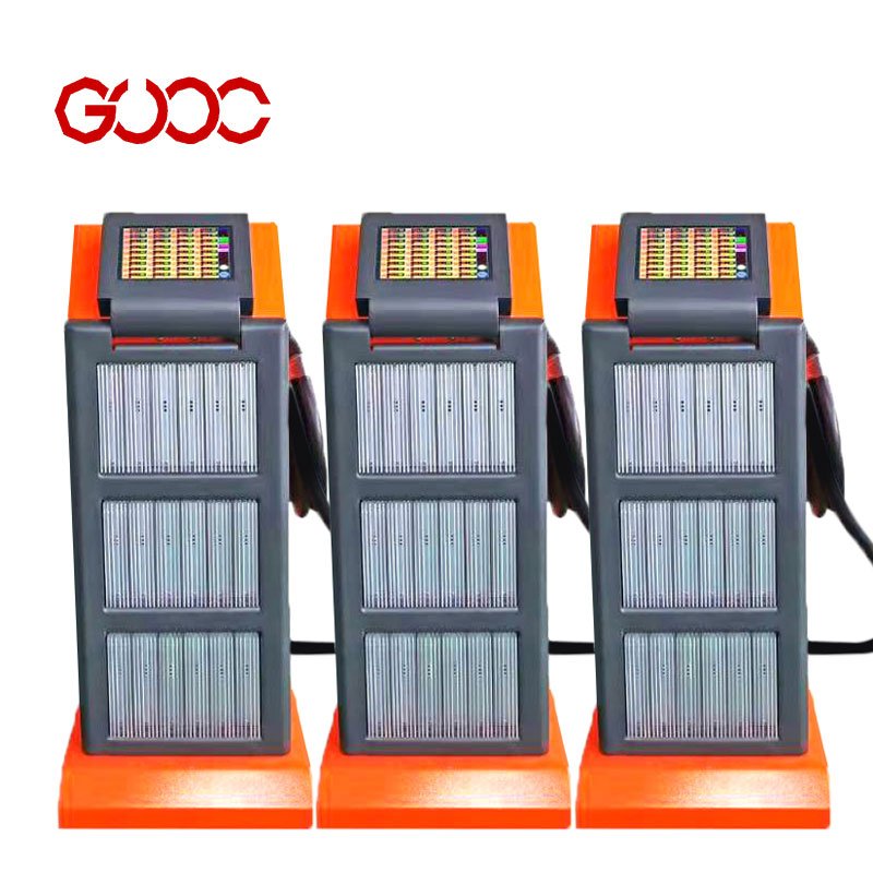
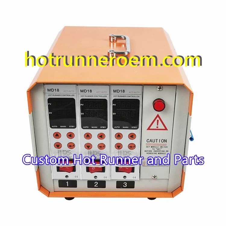
Our hot runner system mold controllers come in modular mainframe designs, letting you choose from single-zone configurations up to multi-zone setups (2, 4, 6, 12+ zones). Each zone card is hot-swappable, so you can replace or upgrade heater modules without shutting down the entire system, ensuring minimal downtime and maximum productivity.
| Zone Options | Description |
|---|---|
| Single-zone | Basic control for one heater |
| Multi-zone (2, 4, 6, 12+) | Scalable control for complex molds |
| Hot-swappable cards | Quick card replacement without power-off |
Control Logic & Interface: Precise and User-Friendly
Our controllers use advanced PID control algorithms to provide precise temperature regulation for each zone. They also feature a soft-start function that guards against thermal shocks, extending heater life. For ease of monitoring, the mainframe includes LED and LCD dual displays, showing real-time temperature data and system status clearly.
- PID control: Keeps temperatures stable and accurate
- Soft-start: Smooth power ramp-up reduces wear on heaters
- LED/LCD displays: Clear visibility of zone status and settings
Electrical Safeguards: Reliable Protection
Robust electrical safeguards protect both your mold and the controller itself. Input and output circuits are shielded with over-current and short-circuit protections, while the system actively monitors thermocouple signals to detect faults like broken sensors or wiring issues early.
- Thermocouple fault detection: Alerts you instantly on sensor failures
- Input/Output protection: Prevents electrical damage and downtime
- Enhances reliability and extends equipment life
For a deeper dive into these controller features, check out our detailed overview on PID hot runner control modules and the full hot runner temperature controller systems.
This modular, protected architecture makes our hot runner system mold controllers a dependable choice for injection molding users worldwide.
The Connectivity Ecosystem: Cables and Connectors
Heavy-Duty Mold Power Cables
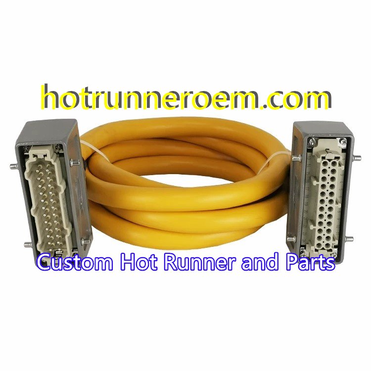
When it comes to hot runner system mold controllers, the power cables are the backbone. We use heavy-duty mold power cables made with carefully selected wire gauges to handle the load without overheating or voltage drops. These cables come with insulation designed to withstand harsh factory conditions—resisting high heat, oil splashes, and abrasion. This durability ensures your hot runner system keeps running smoothly, even in tough injection molding environments.
Thermocouple Data Cables
Accurate temperature control depends on clean signals, so thermocouple data cables are shielded to reduce electrical interference. We support both J-Type and K-Type thermocouples, which are commonly used in molding operations for reliable temperature readings. The shielding and build quality guarantee that your temperature data stays clear and consistent, improving PID control accuracy.
Connector Standards
Industrial rectangular connectors are the industry norm for hot runner communication interfaces, and we adhere strictly to these standards. Our connector sets come in standard pin counts such as 16-, 24-, and 48-pin options, fitting a wide range of controller mainframes and zone cards. The connectors are engineered for secure, quick, and vibration-resistant connections—making installation and maintenance hassle-free. You can get a clear sense of their build and wiring layout in the exploded view diagrams typically provided with our hot runner cable assemblies.
For those interested in the wiring specifics, our molds’ electrical interface solutions cover everything from power feed to thermocouple connections. To explore detailed wiring options, you might find our pages on hot runner controller cables and nozzle thermocouple wiring very useful.
Installation & Wiring Configuration
Standard Wiring Sequences: Zone-to-Pin Mapping & Grounding Protocols
When setting up your hot runner system mold controllers and cables, it’s critical to follow the standardized wiring sequences. Each temperature control zone must be accurately mapped to the corresponding pin on your modular mainframe cabinet. This precise zone-to-pin mapping ensures reliable temperature management across multiple zones. Always adhere to grounding protocols to minimize electrical noise and maintain system safety — proper grounding helps protect sensitive PID hot runner control modules from transient voltage spikes and enhances overall operational stability.
Connection Best Practices: Strain Relief & Cross-Talk Avoidance
To maximize durability and performance, apply strain relief at cable joints and connectors. This reduces mechanical stress on heavy-duty mold power cables and thermocouple interconnect cables, preventing premature wear and connection failures. Also, keep power wiring and temperature sensor cables separated to avoid cross-talk, which can interfere with accurate thermocouple signals (whether J-Type or K-Type). Employ shielded cables and maintain physical distance between industrial heating element wiring and sensor lines whenever possible to ensure clean data transmission and precise temperature control.
For detailed wiring guidance and more on thermocouple connectivity, check out our specialized hot runner temperature sensor wiring solutions to guarantee a smooth installation process tailored to your mold heater connection set.
Manufacturing & Quality Assurance: Reliable Production and Testing
We prioritize rigorous production standards to ensure every hot runner system mold controller set and cable assembly delivers dependable performance. Each cable set undergoes thorough continuity and resistance testing to confirm flawless electrical paths. This step guarantees that the heavy-duty mold power cable and thermocouple interconnect cable meet strict industry criteria before leaving the factory.
For controllers, we conduct intense durability testing by running full-load operations continuously for 24 hours. This real-world stress test validates the endurance of the multi-zone temperature controller and its internal components, including the PID hot runner control module and hot runner zone cards. Such stringent checks ensure your injection molding temperature controller is ready to handle demanding production cycles without failure.
Our commitment to quality not only roots from advanced factory protocols but also from a deep understanding of the industrial heating element wiring environment. This guarantees our products maintain industry-leading reliability, protecting your mold heater connection set investment and minimizing downtime.
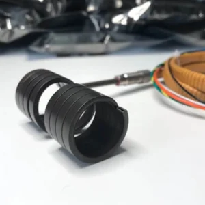
For insight into heater components, you might find our detailed overview on hot runner heater coils useful as a complementary resource on durability and performance factors.
Selection Guide: Matching the Set to Your Mold
Choosing the right hot runner system mold controllers and cables starts with understanding your mold’s needs. Here’s how to align your setup for optimal performance:
A. Determining Zone Requirements
- Count each manifold and nozzle zone separately.
- Each zone requires a dedicated control channel via a multi-zone temperature controller or hot runner zone card.
- Example:
| Component | Zones Counted |
|—————-|———————|
| Manifold | 1-6 zones (common) |
| Nozzle | 1 zone per nozzle |
Make sure the system supports enough zones for both the manifold and nozzle arrays. For complex molds, check if modular expansion cards can be added easily. For detailed nozzle design and manifold info, check our resources on hot runner manifold and nozzle tips.
B. Selecting the Right Amperage
- Match the heater load with 15A or 30A control modules.
- Use 15A modules for standard molds with low-to-medium heater wattage.
- Choose 30A modules when heating elements demand higher current for faster, stable heat-up.
- Example table:
| Heater Load | Recommended Module |
|---|---|
| Up to 3.6 kW | 15A Control Module |
| Above 3.6 kW | 30A Control Module |
Selecting the precise amperage prevents overload, ensuring the controller mainframe runs efficiently and safe.
C. Cable Length Customization
- Standard cable lengths usually cover most setups.
- For larger molds or complex layouts, opt for custom cable lengths to keep wiring tidy and reduce signal loss.
- Cable sets include heavy-duty mold power cables and thermocouple data cables with shielding to prevent interference.
- Consider cable routing and connection points to maintain strain relief and prevent cross-talk issues.
Proper cable length choice protects the system’s electrical interface and enhances durability.
By carefully matching zone count, amperage, and cable length, you get a reliable hot runner control set that fits your injection molding process perfectly.
Troubleshooting & Maintenance for Hot Runner System Mold Controllers and Cables
Common Error Codes: Interpreting Controller Alarms
When working with multi-zone temperature controller systems, understanding the alarms on your hot runner control module is key to fast troubleshooting. Common error codes often point to thermocouple faults, heater circuit failures, or communication issues between zone cards and the modular mainframe cabinet. For example:
- Thermocouple open-circuit fault signals broken or disconnected J-type thermocouple wiring.
- Overcurrent alarm suggests a potential overload on 15-amp or 30-amp control modules.
- Sensor short circuit indicates possible wiring damage or cross-talk between sensor and power cables.
Regularly reviewing and decoding these controller error codes helps avoid unnecessary downtime and ensures your injection molding TCU runs smoothly.
Cable Integrity Checks: Testing Continuity and Damaged Pins
Maintaining heavy-duty mold power cables and thermocouple interconnect cables in prime condition is critical for reliable mold heater connection sets. Here’s how to keep them in check:
- Continuity Testing: Use a multimeter to verify that both heater power cables and sensor wires have no breaks along their length.
- Inspect Connectors: Look carefully at industrial rectangular connectors—especially 16-, 24-, or 48-pin types—to make sure none of the pins are bent, corroded, or loose.
- Avoid Cross-Talk: Confirm that mold power cables and thermocouple data cables are routed separately with proper shielding to prevent interference, which can cause erratic temperature readings.
Regular cable integrity checks prevent unexpected failures and extend the lifespan of your hot runner cable assembly. For precise wiring techniques and maintenance tips, you can explore our hot runner mold components for additional support and resources.
 English
  Spanish
  French
  Portuguese
  Italian