 Skip to content
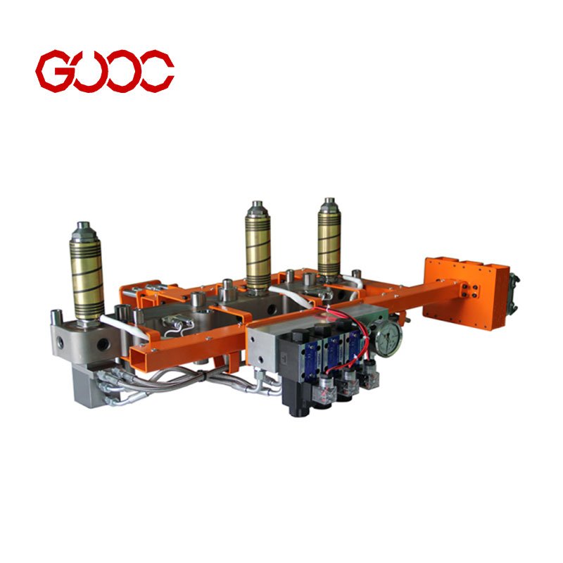
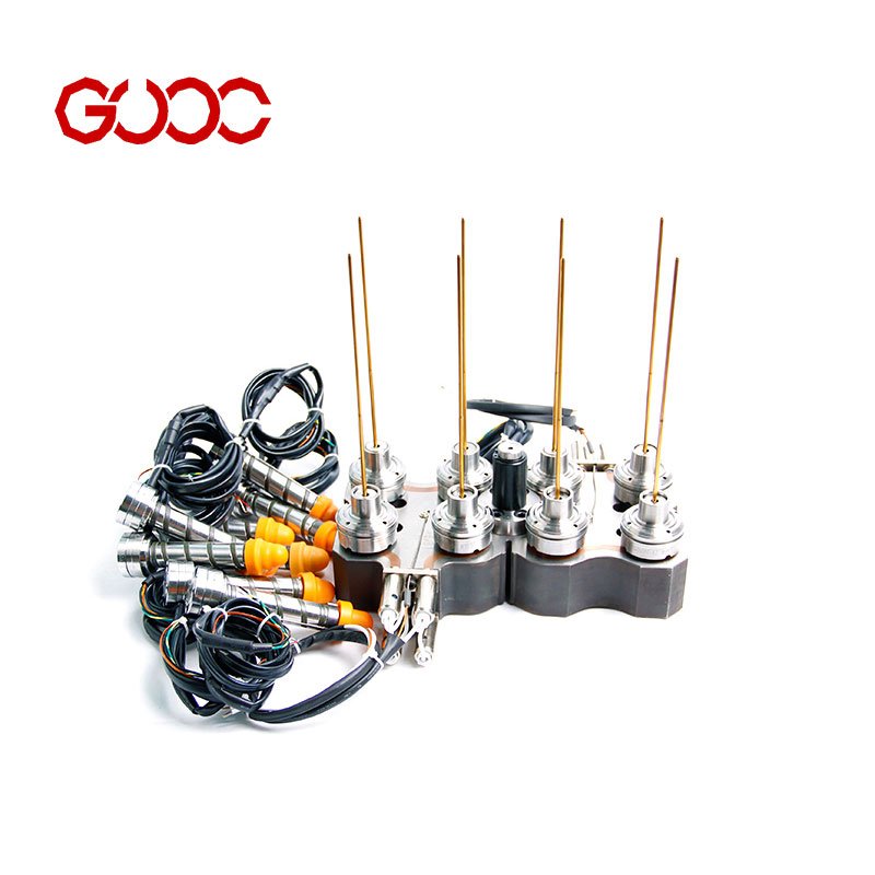
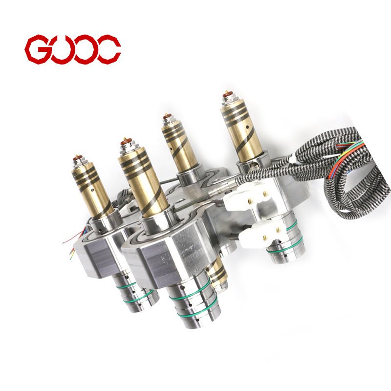
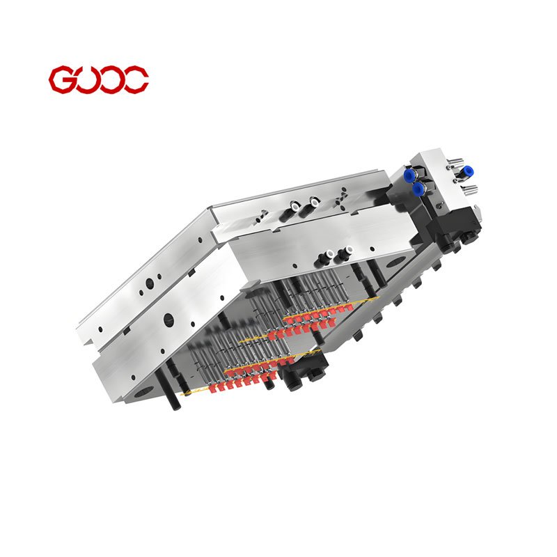
Understanding Custom Hot Runner Systems
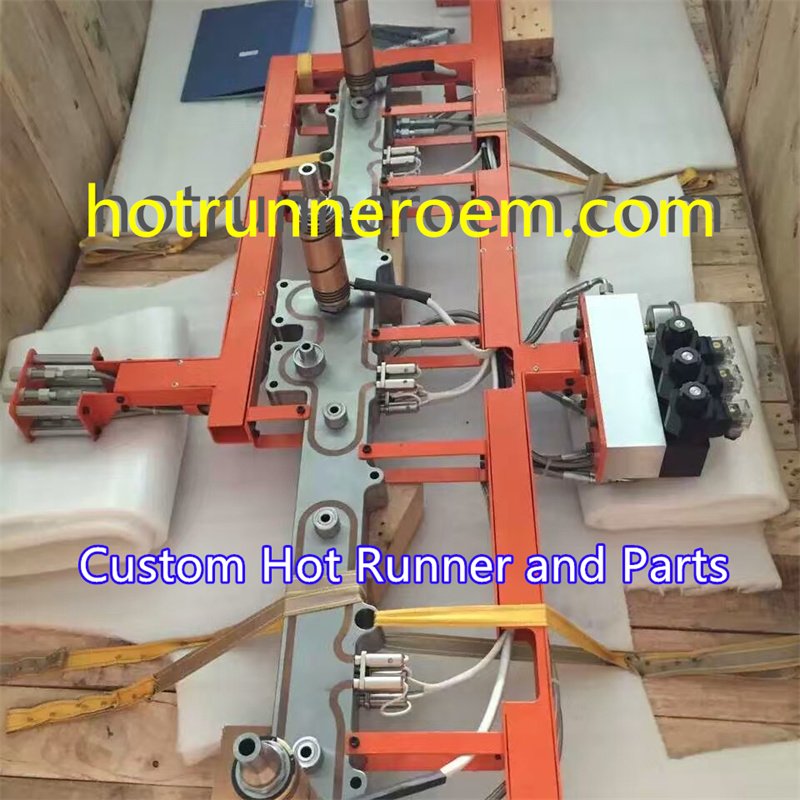
Injection molding projects often run into the same problems: poor filling balance, resin mismatch, long trial time, and unstable part quality. A custom hot runner system solves this by matching the gate type, mold layout, and material requirements to the real application.
Core Components and Working Principles
| Component | Role |
|---|---|
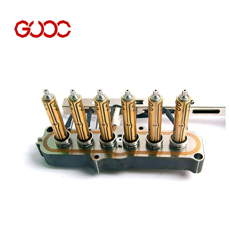
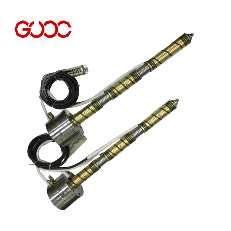
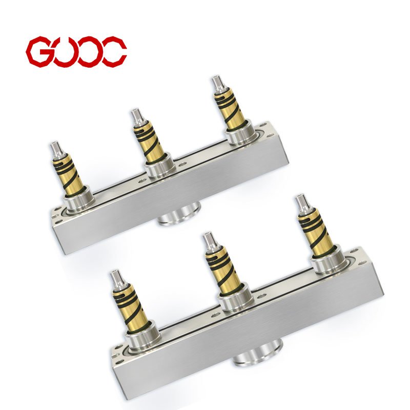
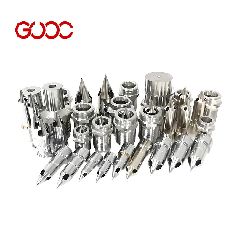
| Hot runner nozzle | Delivers melt into the cavity through the selected gate type. |
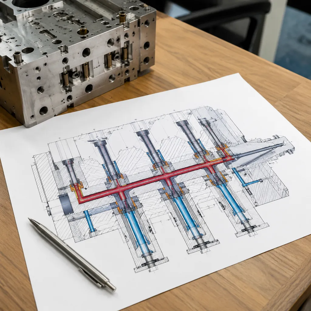
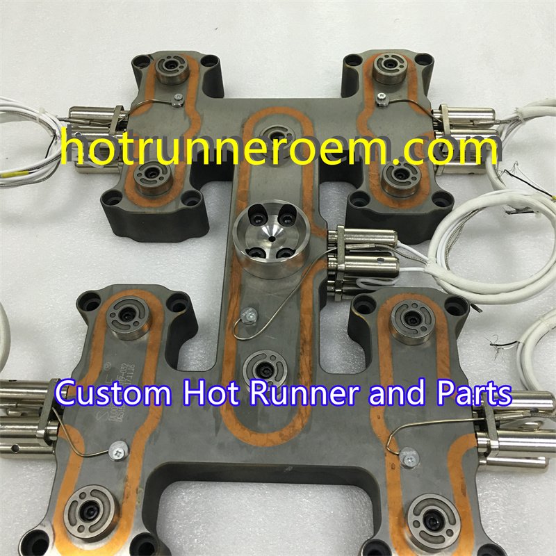
| Manifold block | Distributes melt flow to each nozzle in the system. |
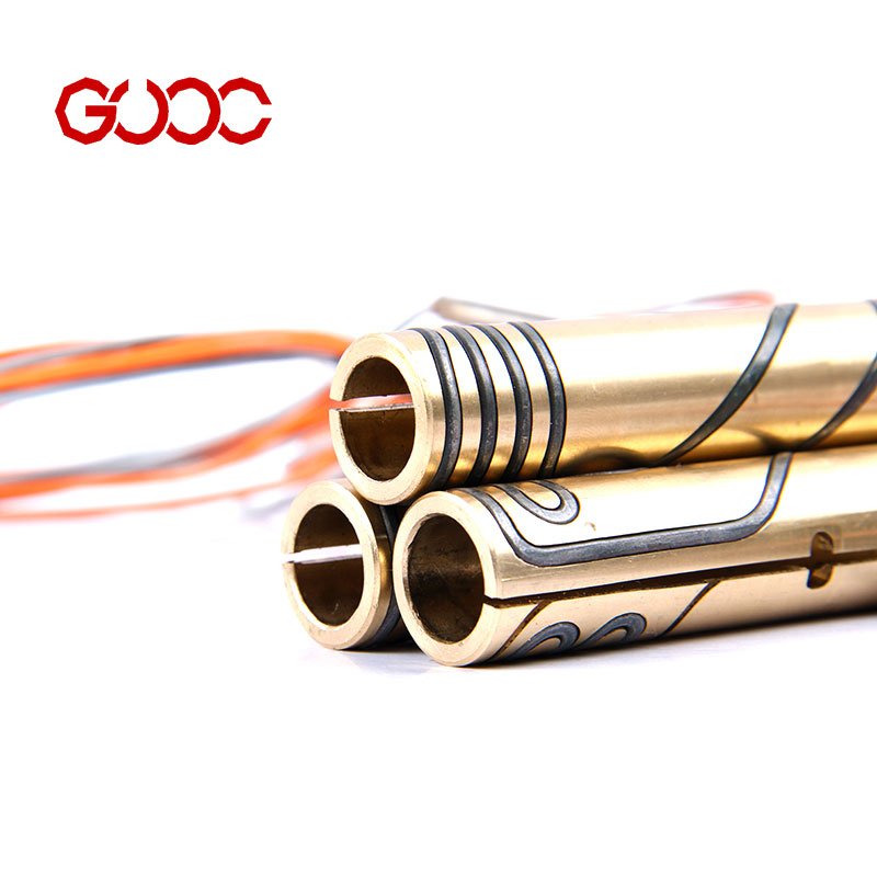
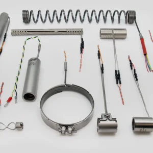
| Heating tubes | Keep melt temperature stable during processing. |
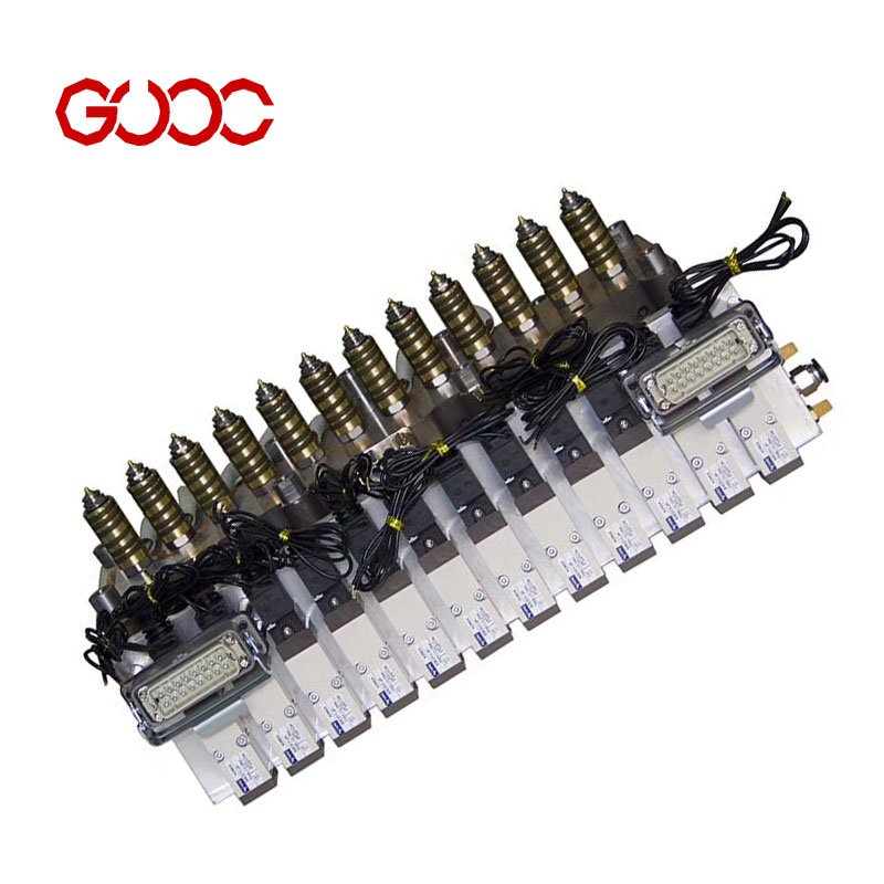
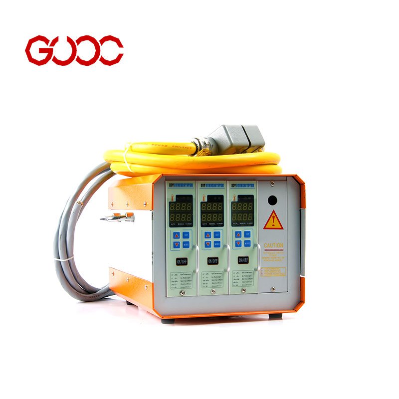
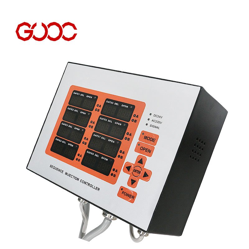
| Controller | Supports temperature and injection sequence control. |
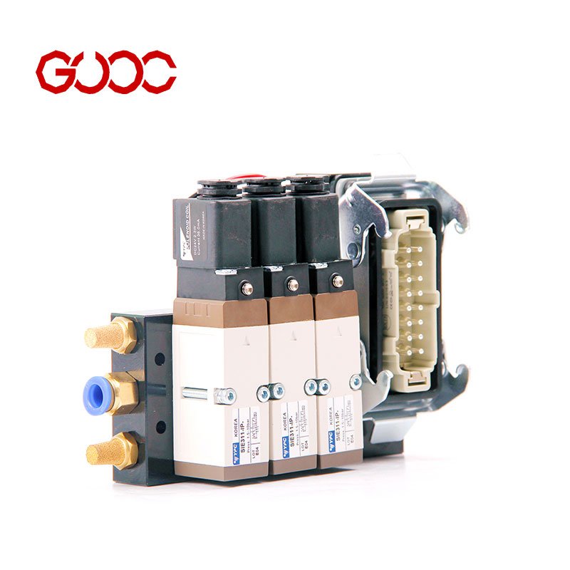
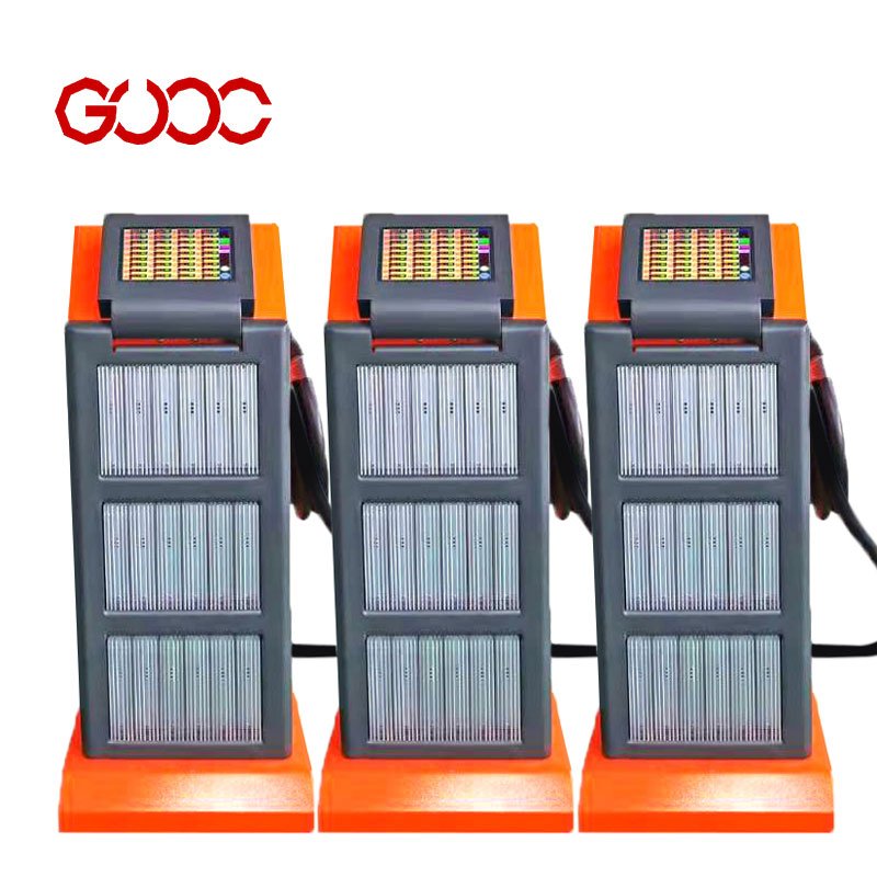
| Control modules | Include integrated temperature controllers, sequence injection timer controllers, and cylinder control modules. |
The working idea is simple: plastic melt moves through the manifold, stays heated, and reaches the gate with controlled flow. That is why pressure drop, residence time, and flow balance matter so much in a custom design.
Benefits of Custom Systems for Injection Molding
- Better fit for the mold — designed for the part, gate position, and cavity layout.
- Material-specific support — suitable for materials such as PP, PFA, PES, PC, PA10T + 30% GF, PBT + 30% GF, PMMA, and PEI ULTEM 1000.
- Flexible structure — supports valve gate, open gate, hot half, extended nozzle, integrated, and assembled systems.
- Technical speed — DFM analysis and quote feedback are provided within 12–24 hours.
- Fast project turnaround — samples can be ready in 10 days, with production orders often completed in 25 days.
- Quality control — 100% final inspection per lot, hourly online QC, and technician self-inspection.
- Confidential handling — NDA support is available before drawing transfer to protect trade secrets.
As a hot runner system manufacturer, we focus on practical OEM design, stable processing, and reliable delivery for global injection molding needs.
Plastic Material Properties Required for Customization
Resin Type and Thermal Degradation Sensitivity
Choosing the right resin type is crucial for a custom hot runner system. Different materials have varying sensitivities to heat, which affects how they degrade during processing. For example, PFA and other Teflon series resins are highly heat-resistant, making them suitable for high-temperature applications without losing their properties. Understanding a resin’s thermal degradation behavior ensures that the hot runner nozzle and manifold components can be designed to withstand the specific heat levels without compromising performance. This knowledge helps prevent issues like melting, discoloration, or loss of mechanical strength during injection molding. For detailed resin compatibility, consult hot runner thermocouple and heater suppliers.
Melt Flow Rate and Viscosity Profile
The melt flow rate (MFR) and viscosity profile of a resin directly impact how it flows through the hot runner system. A resin with a high MFR flows easily, reducing injection pressure loss and ensuring consistent filling. Conversely, low MFR materials may require a more precisely engineered flow channel and manifold sizing to prevent pressure drops and shear rate issues. Proper control of melt viscosity helps optimize residence time and melt volume flow rate, which are key to achieving uniform part quality and minimizing molding shrinkage. Accurate data on viscosity profiles allows us to design flow channels that balance pressure and shear forces, improving overall molding efficiency.
Additives, Colorants, and Filler Content
Adding fillers, colorants, or other additives can significantly alter a resin’s flow characteristics and thermal behavior. Fillers like glass fibers increase specific gravity and improve mechanical strength but also raise shear rate and pressure drop in the system. Colorants and other additives may affect melt temperature and viscosity, requiring adjustments in the hot runner design to maintain optimal flow and prevent clogging. These modifications are essential for achieving the desired surface finish, gate grade, and dimensional stability. Tailoring the hot runner system to accommodate such variations ensures reliable production and high-quality parts.
Part Design and Mold Layout Data Needed
For a custom hot runner system technical review, I start with the part and mold layout data first. That is what tells us the right hot runner nozzle setup, manifold block size, and whether the design needs tighter control on pressure drop, residence time, or shear rate. When the input data is clear, the quote and DFM result are much more stable.
Part Weight, Shot Size, and Wall Thickness
- Part weight shows how much melt the system must deliver.
- Shot size helps match the melt volume flow rate to the mold demand.
- Wall thickness affects filling balance, molding shrinkage, and injection pressure loss.
Thin-wall parts usually need a faster, cleaner melt path, while thicker parts need better heat control to avoid long residence time. This is where a custom hot runner system manufacturer has to look at the full part behavior, not just the drawing.
Number of Cavities and Pitch Layout
- Cavity count sets the basic layout and flow split.
- Pitch controls nozzle spacing and mold plate interfaces.
- Layout also affects balancing, service access, and controller routing.
More cavities do not just mean more nozzles. They also change the manifold block size, the flow balance, and the amount of space available around each gate. For related hot runner components and fit-up parts, I keep the hot runner parts range aligned with the mold layout from the start.
Target Production Cycle Time
- Cycle time target drives how fast the system must heat and recover.
- It helps define the control zones and response speed.
- It also affects gate choice and the level of thermal stability needed.
Short cycle work needs a system that can keep flow consistent without adding excess heat or delay. Longer cycles give more room, but the design still has to protect the melt quality and keep the process steady across the full run.
Gate Selection and Design Specifications
When I design a custom hot runner system technical package, gate choice is one of the first things I lock down. It affects fill balance, pressure drop, injection pressure loss, part look, and molding shrinkage. I match the gate to the resin, the mold layout, and the finish target, not just to the part shape.
Thermal Open Gate vs. Valve Gate Requirements
| Item | Open Gate | Valve Gate |
|---|---|---|
| Best use | Simple flow paths and general molding needs | Better control for appearance, filled resins, and tighter process control |
| Flow control | Direct melt flow | Melt flow is opened and closed by a valve pin |
| Part mark | Can be more visible | Usually cleaner gate control |
| Process focus | Stable melt delivery | Better control of injection timing and gate sealing |
For the gate structure itself, I keep the nozzle and tip match clear from the start. A proper hot runner system nozzle design helps reduce flow issues and keeps the melt path clean. For valve gate projects, I use a setup that fits the mold and the control method, which is why I keep the gate design tied closely to the overall system design.
Gate Location and Surface Finish Expectations
Gate location is not just about filling the cavity. I look at:
- Flow balance
- Visible gate mark
- Shear rate
- Residence time
- Surface finish needs
A bad gate position can raise melt volume flow rate problems and leave more stress in the part. For parts with stricter appearance needs, I place the gate where it supports cleaner filling and a lower risk of mark issues. I also keep the gate area aligned with the mold finish target so the final look stays consistent.
Valve Gate Actuation Type
| Actuation Type | Typical Use | Design Focus |
|---|---|---|
| Pneumatic | Common in controlled gate movement | Fast, simple gate motion |
| Hydraulic | Used where stronger force is needed | High gate closing force |
| Electric | Used in control-focused systems | Precise movement control |
For valve gate systems, the actuation method has to match the mold layout and the control setup. I design the system around reliable gate timing and stable closing action. In practice, the choice depends on the mold design, the resin behavior, and the process control target.
For valve gate construction details, the needle valve hot runner valve system is a useful reference point for how gate motion and sealing are handled in a technical hot runner layout.
Manifold Architecture and Flow Channel Requirements
A manifold block has to do three things well: balance flow, keep pressure drop under control, and avoid excess residence time. When those points are missed, injection pressure loss goes up, fill balance gets uneven, and part quality can shift.
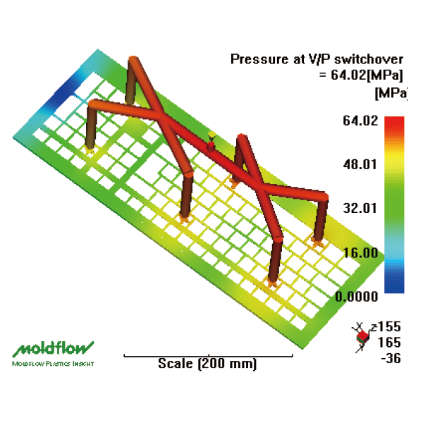
I start with mold flow analysis for the layout, then shape the runner path around the part, cavity count, and resin behavior. For complex builds, I also review custom hot runner manifold designs early so the flow channel stays practical from the start.
Flow Balance and Sizing
Flow balance is about getting melt to every cavity at the right time. The manifold size, hot runner nozzle layout, and channel path all affect that.
| Check point | What I look at | Why it matters |
|---|---|---|
| Runner path | Length and symmetry | Keeps fill even |
| Manifold block size | Melt capacity and layout fit | Supports stable flow |
| Nozzle count | Match to cavity plan | Reduces imbalance |
| Resin behavior | Melt volume flow rate, specific gravity, shear rate | Helps size the system correctly |
Pressure Drop and Melt Speed
I keep pressure drop low enough to avoid unstable filling. Too much restriction can raise injection pressure loss and make the process harder to hold.
Key points I review:
– Smooth melt path through the manifold block
– Short, direct routes where possible
– Controlled melt velocity in the hot runner nozzle
– Stable gate feed without extra drag
Residence Time Control
Residence time matters because melt that sits too long can lose stability. I aim for a volume that moves cleanly through the system without dead zones.
I check:
– Melt hold-up inside the manifold
– Extra pockets that trap material
– Heat exposure across the full flow path
– Resin sensitivity, including tip grade and molding shrinkage risk
For a cleaner setup, I use mold flow analysis for hot runner systems to verify flow balance, pressure drop, and residence time before production.
Mold Integration and Electrical Control Specifications
When I handle custom hot runner system technical details, I start with the mold interface and the control setup. A good fit here keeps the hot runner nozzle, manifold block, and wiring layout clean, while helping stabilize pressure drop, residence time, and melt flow.
Mold Plate Dimensions and Physical Interfaces
The mold plate layout has to match the hot runner structure before production starts. I check the space for the manifold, nozzle positions, mounting points, and cable routing so the system fits the mold without forcing changes later.
| Check Item | What I Verify |
|---|---|
| Mold plate size | Enough space for the hot runner structure |
| Nozzle position | Matches the gate and cavity layout |
| Manifold area | Fits the manifold block cleanly |
| Physical interface | Mounting points and access paths stay practical |
Thermal Control Zones and Sensor Types
Temperature control is a big part of hot runner system manufacturer work. I set the thermal zones around the mold layout so heat stays stable across each channel and nozzle. That helps keep melt behavior steady and supports consistent part quality.
Key points I keep in mind:
- Zone count should match the mold design
- Sensors need to work with the controller setup
- Stable heat control helps reduce molding shrinkage
- Better control supports smoother melt flow and lower risk of unstable melt volume flow rate
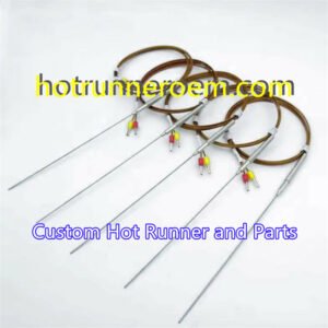
For precise heating control, I use solutions such as hot runner temperature controllers and multi-zone PID temperature control when the mold layout needs tighter thermal balance.
Controller Compatibility and Power Requirements
The controller must match the hot runner system, heating tubes, and zone layout. I keep the setup practical and simple: the controller type, wiring plan, and power setup should all fit the mold and the production site.
| Control Item | What It Must Match |
|---|---|
| Controller type | Integrated temperature control or other required module |
| Zone layout | Number of heat zones in the mold |
| Heating parts | Heating tubes and connected components |
| Site setup | Factory power and control cabinet layout |
I also align the controller choice with the needed response for the process, especially when the mold uses a valve gate setup or a more complex thermal arrangement. This keeps the system stable and easier to run in daily production.
 English
  Spanish
  French
  Portuguese
  Italian