 Skip to content
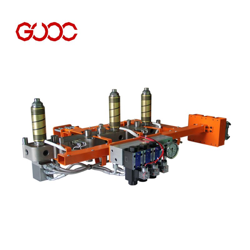
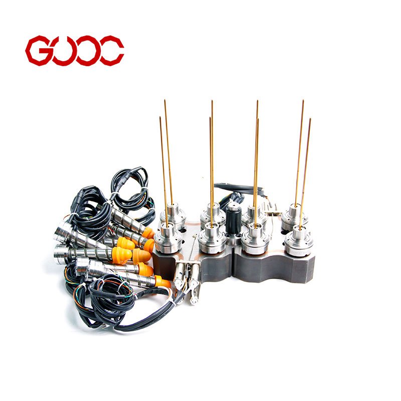
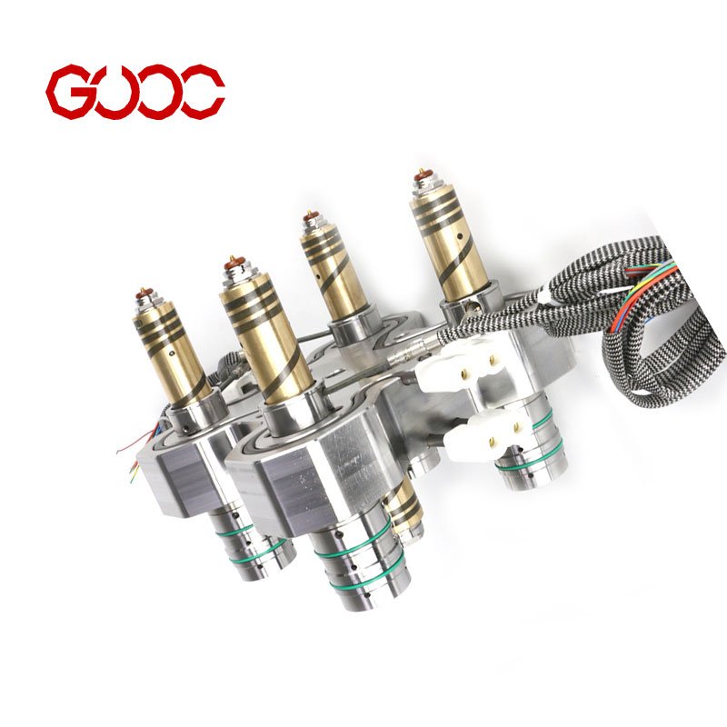
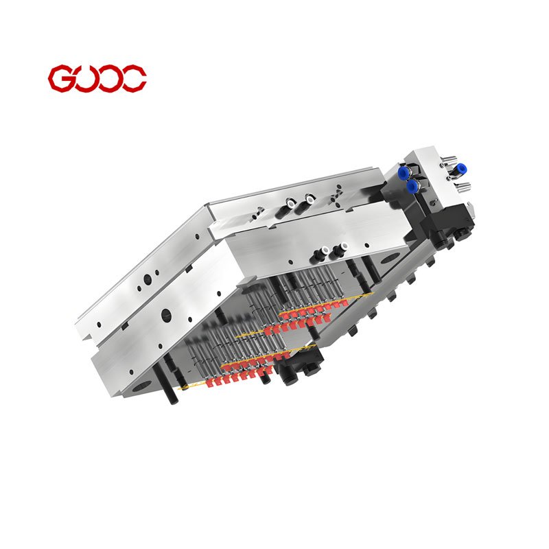
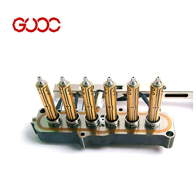
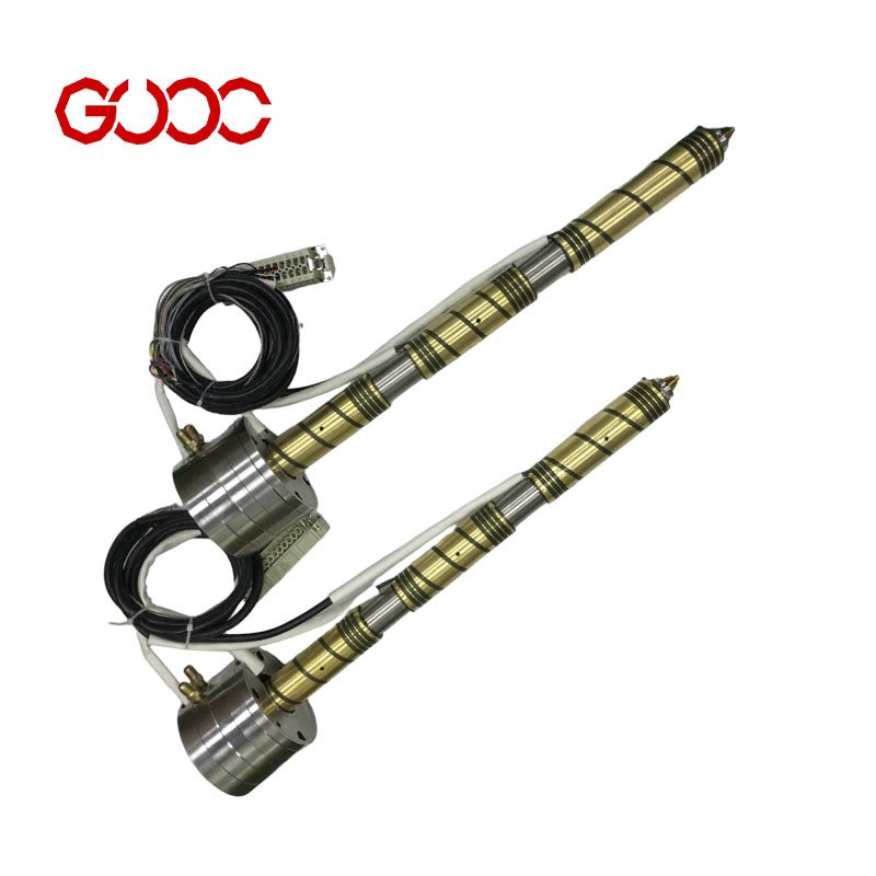
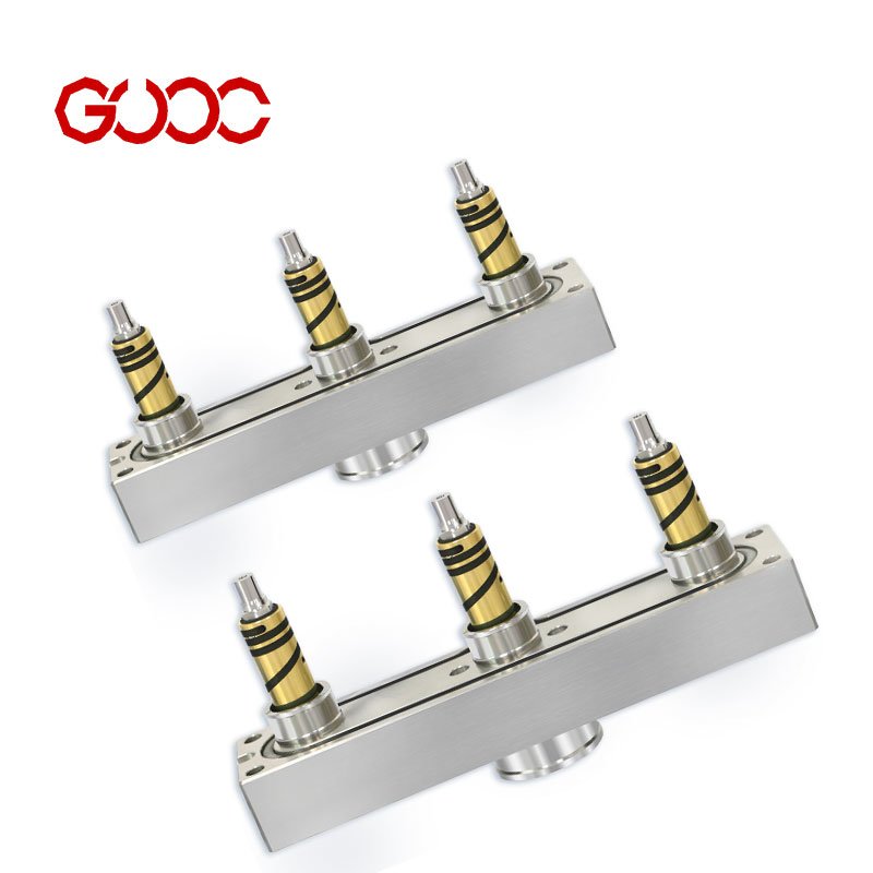
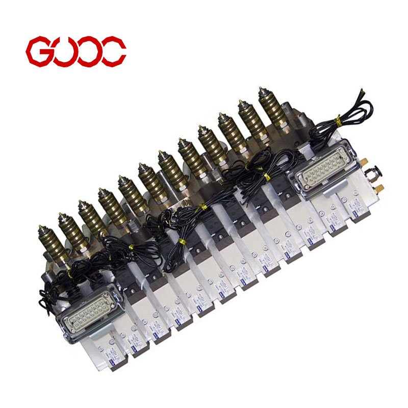
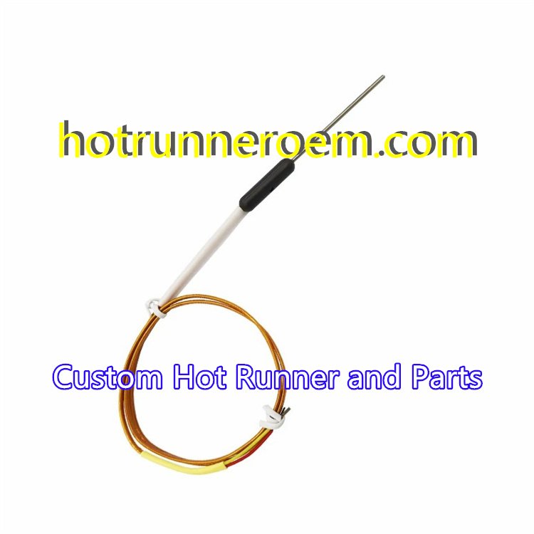
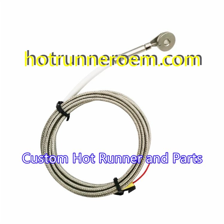
Hot Runner Temperature Sensor Overview
Injection Molding Control
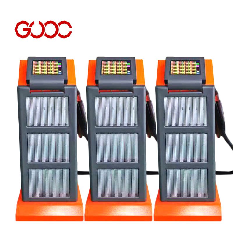
Temperature consistency is critical in every hot runner system. Our hot runner temperature sensor solutions support thermal monitoring for valve gate and open gate applications, helping manufacturers maintain stable process conditions across manifolds, nozzles, and related control components.
Multi-Drop Mold Applications
For multi-drop molds, each zone requires dependable temperature feedback to support repeatable molding performance. We provide OEM support for hot runner systems used with materials including:
- PP
- PC
- PBT + 30% GF
- PA10T + 30% GF
- PMMA
- PEI ULTEM 1000
- PFA and PES
Responsive Thermal Monitoring
A properly integrated hot runner temperature sensor works with a temperature control box or integrated controller to monitor mold heating conditions during production. Our engineering team supports custom hot runner spare parts, system components, and control accessories based on project drawings and application requirements.
Hot Runner Temperature Sensor Specifications
We supply hot runner temperature sensor solutions as part of our custom OEM hot runner accessories program. Each sensor requirement is reviewed against the mold drawing, nozzle layout, and controller connection requirements before production.
| Sensor Requirement | Our OEM Approach |
|---|---|
| Standard sensor needs | Built to match the supplied project requirements |
| Heavy-duty applications | Reviewed according to mold operating conditions and installation details |
| Custom replacement sensors | Made from drawings, samples, or confirmed dimensions |
| Probe size and length | Customized to the required mold location |
| Lead length and routing | Matched to the specified connection layout |
| Junction configuration | Confirmed during engineering review |
| Controller connection | Coordinated with the temperature control box or module |
Probe and Lead Options
Probe diameter, sheath construction, junction style, lead insulation, and operating limits are project-specific. We do not apply unverified standard values to a hot runner thermocouple. Instead, our engineering team confirms the required details through CAD files, drawings, samples, or technical specifications.
For complete sensor and heater sourcing, see our hot runner thermocouple and heater manufacturing support.
Custom Specification Review
We support custom hot runner spare parts for valve gate and open gate systems, including sensor-related requirements that must fit existing nozzles, manifolds, and temperature control equipment. Submit your design data for OEM review, with NDA protection available before project evaluation.
Hot Runner Temperature Sensor Calibration
Correct calibration must match the temperature controller and the molding application. We review the required sensor and controller connection details during OEM design and DFM analysis to help avoid mismatched replacement parts.
Our published product information does not define standard Type J, Type K, or RTD configurations. Calibration type, sensor construction, and control-box compatibility should therefore be confirmed against the project drawing or existing system specification. See our hot runner temperature sensor solutions for custom inquiry support.
J, K, and RTD Selection
- Type J thermocouple: Confirm against the installed controller specification.
- Type K thermocouple: Confirm against the installed controller specification.
- RTD sensor: Confirm resistance and controller input requirements before production.
- Custom replacement sensor: Provide drawings, samples, or connection details for engineering review.
Grounded vs. Ungrounded Junctions
Junction configuration affects how a hot runner temperature sensor connects and responds within the system. Grounded and ungrounded options must be selected to match the existing controller, wiring arrangement, and mold design.
We support custom OEM processing with NDA protection before drawing review. Each order follows inspection procedures, including technician checks, hourly online QC, and final inspection for every lot.
Hot Runner Temperature Sensor Mounting
A hot runner temperature sensor must fit the mold layout, nozzle area, and control arrangement without creating installation issues. We review 2D/3D drawings and project requirements to support custom hot runner spare parts for new builds and replacement applications.
| Mounting style | Typical mold integration focus |
|---|---|
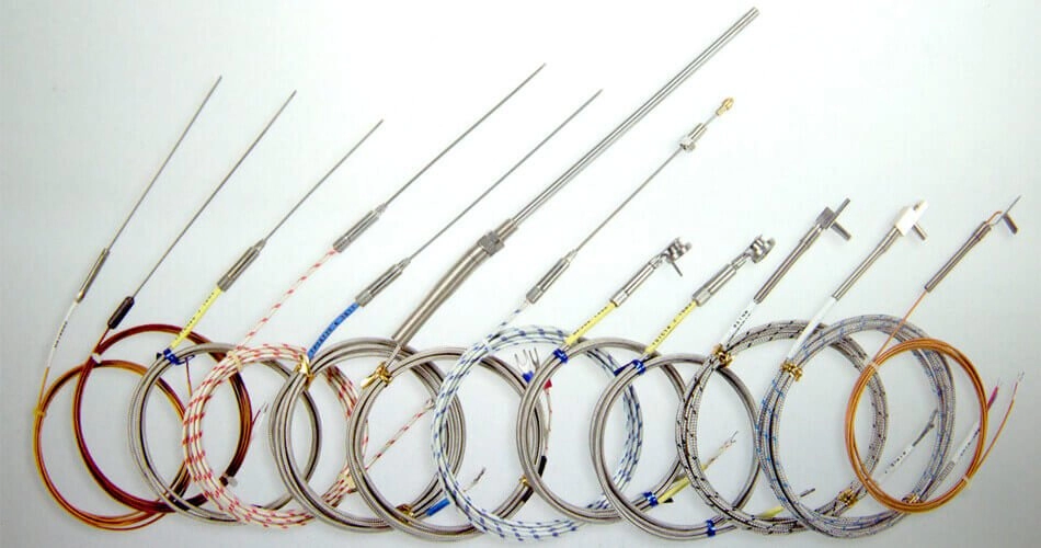
| Direct press-fit probes | Compact installation where the sensor is fitted directly into the required mold location |
| Mineral insulated probes | Sensor configurations requiring protected probe construction for hot runner use |
| Bayonet fitting sensors | Adjustable, retained mounting for locations that need secure positioning |
| Ring / washer thermocouples | Surface-contact temperature monitoring around a designated mounting point |
| Leaf spring mounts | Spring-supported contact where consistent sensor positioning is required |
| Flange mounts | Fixed mounting arrangements based on the mold design and available space |
For every hot runner temperature sensor project, we match the form factor to the drawing, component interface, and temperature control setup. This supports integration with custom hot runner mold systems and related controller accessories without relying on a one-size-fits-all sensor layout.
Custom mounting support includes:
- Probe length and installation position based on supplied drawings
- Sensor mounting configuration for hot runner nozzles, manifolds, or mold components
- Fitment review during DFM analysis
- OEM processing, assembly, and final quality inspection for each production lot
Heavy-Duty Cable Protection & Termination Options
Cable routing can affect the reliability of every hot runner temperature sensor. We review lead protection and termination requirements with the complete mold layout, temperature control box, and service environment in mind.
| Requirement Area | Custom Engineering Review |
|---|---|
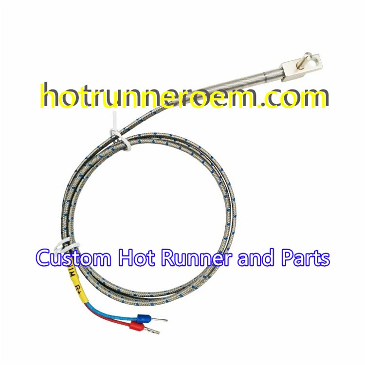
| Cable sheathing | Stainless steel overbraid, square-lock armor, and Kapton/PTFE lead requirements can be reviewed against routing, abrasion, and heat exposure needs. |
| Lead length | Sensor lead lengths can be specified to suit the mold, manifold, nozzle, or controller connection point. |
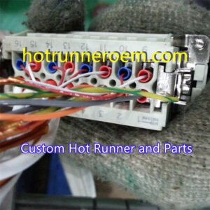
| Termination | Miniature plugs, spade lugs, and multi-pin connector requirements can be matched to the customer’s existing connection layout. |
| Controller connection | We support project-based integration with temperature control equipment and related hot runner controller cables. |
Cable Protection
For custom hot runner spare parts, cable protection is defined around the actual installation conditions. Our engineering team reviews the sensor routing path, available space, connection method, and required service access before production.
- Stainless steel overbraid: Reviewed where additional external lead protection is required.
- Square-lock armor: Considered for demanding cable-routing conditions.
- Kapton/PTFE insulation: Evaluated when the project requires insulation suited to the mold environment.
Termination Options
A hot runner temperature sensor must connect correctly to the control system. We can review the required termination format from your drawing, sample, or existing wiring arrangement.
| Termination Type | Typical Integration Need |
|---|---|
| Miniature plugs | Direct connection to compatible temperature-control wiring |
| Spade lugs | Terminal-based wiring arrangements |
| Multi-pin connectors | Organized connections for multi-zone mold systems |
For accurate matching, provide the existing connector details, cable layout, and controller interface requirements with the project inquiry.
System Integration & Controller Compatibility
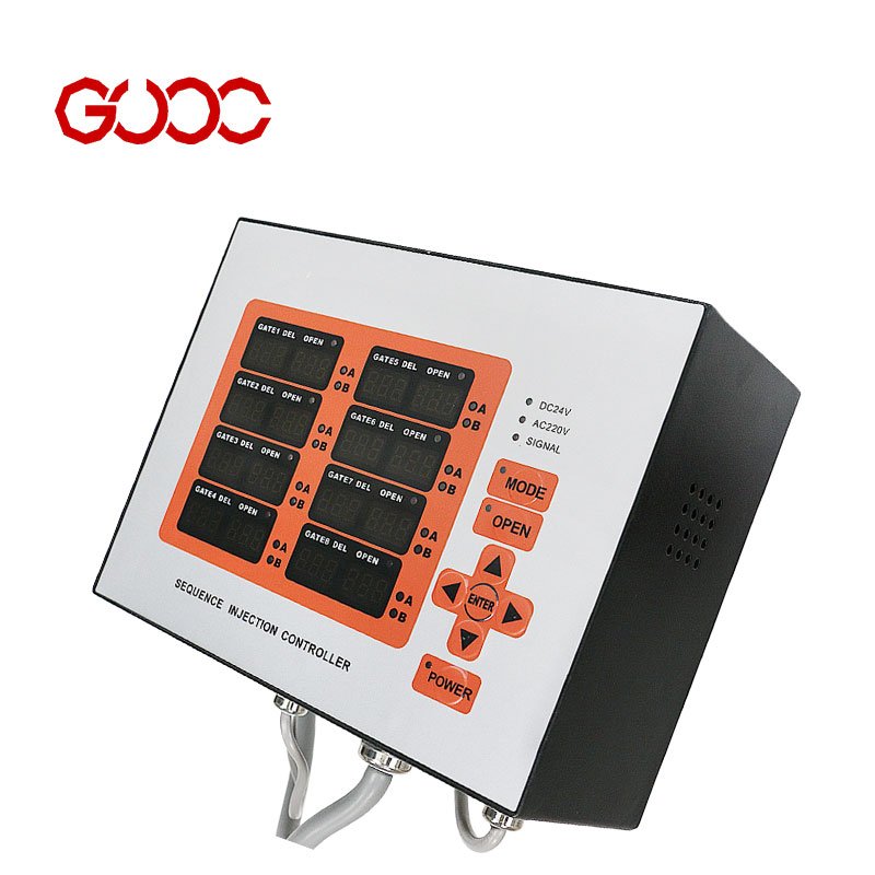
A hot runner temperature sensor must match the control box wiring and zone layout to provide stable temperature feedback. We support custom hot runner projects with integrated temperature controllers, temperature control boxes, and multi-zone control arrangements.
Wiring Identification
ANSI, IEC, and JIS color conventions can differ by market and controller configuration. We verify sensor lead identification, polarity, and connection requirements against the approved project drawing and controller specification rather than relying on wire color alone.
Multi-Zone Wiring
For multi-drop molds, each sensing point must be assigned to the correct controller zone. We support OEM design review for:
- Zone-by-zone sensor identification
- Pinout confirmation for multi-zone connections
- Junction box and controller wiring layout review
- Integration with a 12-zone hot runner controller or other project-specific control setup
Accurate wiring documentation helps prevent zone mismatch during mold assembly, commissioning, and maintenance.
Custom OEM Hot Runner Temperature Sensors
We manufacture custom hot runner temperature sensor solutions for replacement parts, new mold projects, and OEM supply. Our team can build sensors around your drawing, sample, or system requirements, with custom probe lengths, diameters, lead arrangements, and connection details matched to the intended hot runner assembly.
- Custom dimensions for sensor fitment and mold space
- Lead configurations aligned with temperature control equipment
- OEM processing for hot runner nozzles, manifolds, and related components
- Support for custom sample orders and volume sourcing
Our hot runner components manufacturing capability supports coordinated sourcing of temperature-related accessories and other custom hot runner spare parts.
Engineering Support and Production
We review project requirements with 2D or 3D CAD files and provide a quotation with DFM analysis within 12–24 hours. An NDA can be signed before drawing review to protect project information.
Our standard process includes:
- CAD file or project inquiry submission
- Quotation and DFM review
- OEM production, assembly, and inspection
- International express shipment
Sample production is generally completed in about 10 days, while full orders typically require 10–25 days, depending on project requirements. Each custom hot runner temperature sensor order follows our inspection process before shipment.
Hot Runner Temperature Sensor Quality Control
A hot runner temperature sensor must fit the specified assembly and support consistent system setup. We apply technician self-inspection, hourly online QC checks, and 100% final inspection for every lot before shipment.
Our inspection capability includes precision equipment such as:
- VMS-4030E measurement system
- HR-150A hardness tester
- TESA Hite height measurement equipment
- Mitutoyo SJ400 surface measurement equipment
- Mitutoyo coolant-proof gauges
- HEX-10 HRC inspection equipment
For complete projects, inspection requirements are coordinated with the selected hot runner control system and custom assembly specifications.
Documentation and Project Control
We protect customer drawings under an NDA before project review. Each hot runner temperature sensor project is managed against the approved drawing, requirements, and production process. Electrical, dielectric, traceability, and calibration documentation requirements should be confirmed during the quotation and DFM review, as these specifications depend on the custom application.
Technical FAQs: Hot Runner Temperature Sensors
Type J vs. Type K
How do I choose between a Type J and Type K thermocouple for my hot runner system?
We recommend matching the hot runner temperature sensor to the calibration and input requirements of your existing controller. Type J, Type K, RTD, and other calibration details must be confirmed from the controller documentation or the original sensor specification before production. Our engineering team can review CAD files, samples, and system requirements for custom replacement parts.
For related heating and sensing components, see our hot runner thermocouple and heater solutions.
Early Sensor Failure
What causes a hot runner thermocouple to fail prematurely?
Common causes include damage during mold installation or maintenance, lead damage, poor routing, connection issues, and conditions that do not match the sensor or controller setup. Accurate fitment and inspection are important for stable hot runner operation.
We apply technician self-checks, hourly online QC, and 100% final inspection for each production lot.
Custom Replacement Sensors
Can you manufacture custom replacement sensors for existing hot runner systems?
Yes. We support OEM and custom hot runner spare parts based on supplied drawings, dimensions, samples, or project requirements. Our capabilities include 2D/3D design support, DFM review, CNC processing, assembly, and inspection.
| Custom Support | Our Process |
|---|---|
| Existing system replacement | Review drawings, samples, and fitment requirements |
| Custom sensor configuration | Confirm requirements with the hot runner system and control box |
| Drawing protection | NDA available before project review |
| Quote and DFM | Normally provided within 12–24 hours |
| Production timing | Samples in about 10 days; general orders in 10–25 days |
Grounded vs. Ungrounded Sensors
Should I use grounded or ungrounded sensors for my control box?
The correct junction configuration depends on the control box input, wiring arrangement, and existing hot runner system design. We do not recommend changing sensor configuration without confirming compatibility with the controller and original mold setup.
Our hot runner temperature controller manufacturing support helps customers align custom hot runner temperature sensor requirements with integrated controllers and temperature control boxes.
 English
  Spanish
  French
  Portuguese
  Italian